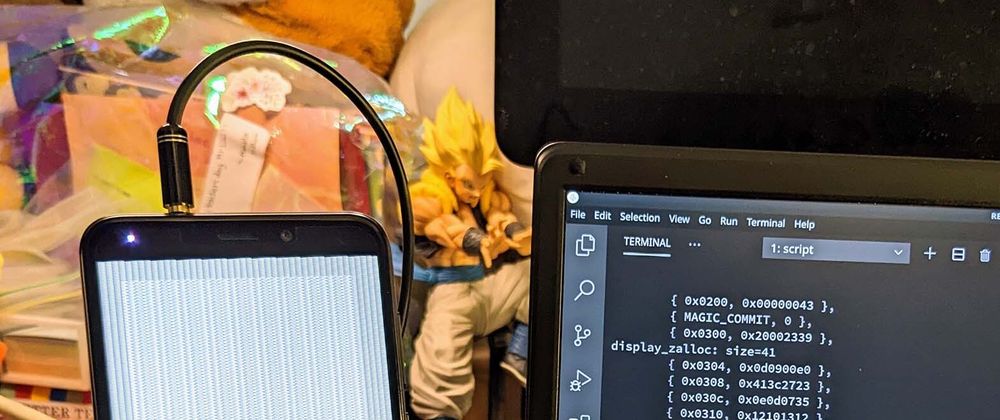
In our last article we talked about Pine64 PinePhone (pic above) and its LCD Display, connected via the (super complicated) MIPI Display Serial Interface...
Today we shall create a PinePhone Display Driver in Zig... That will run on our fresh new port of Apache NuttX RTOS for PinePhone.
If we're not familiar with the Zig Programming Language: No worries! This article will explain the tricky Zig parts with C.
Why build the Display Driver in Zig? Instead of C?
Sadly some parts of PinePhone's ST7703 LCD Controller and Allwinner A64 SoC are poorly documented. (Sigh)
Thus we're building a Quick Prototype in Zig to be sure we're setting the Hardware Registers correctly.
And while rushing through the reckless coding, it's great to have Zig cover our backs and catch Common Runtime Problems.
Like Null Pointers, Underflow, Overflow, Array Out Of Bounds, ...
Will our final driver be in Zig or C?
Maybe Zig, maybe C?
It's awfully nice to use Zig to simplify the complicated driver code. Zig's Runtime Safety Checks are extremely helpful too.
But this driver goes into the NuttX RTOS Kernel. So most folks would expect the final driver to be delivered in C?
In any case, Zig and C look highly similar. Converting the Zig Driver to C should be straightforward.
(Minus the Runtime Safety Checks)
Zig or C? Lemme know what you think! 🙏
Let's continue the journey from our NuttX Porting Journal...
LCD Display on PinePhone Schematic (Page 2)
PinePhone LCD Display
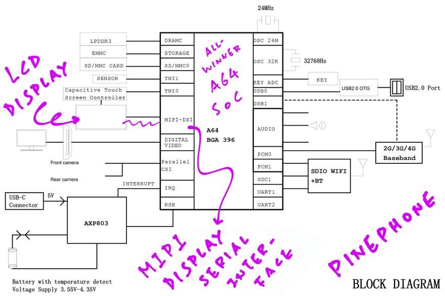
How is the LCD Display connected inside PinePhone?
Inside PinePhone is a XBD599 LCD Panel by Xingbangda (pic above)...
The LCD Display is connected to the Allwinner A64 SoC via a MIPI Display Serial Interface (DSI).
(MIPI is the Mobile Industry Processor Interface Alliance)
What's a MIPI Display Serial Interface?
Think of it as SPI, but supercharged with Multiple Data Lanes!
PinePhone's MIPI Display Serial Interface runs on 4 Data Lanes that will transmit 4 streams of pixel data concurrently.
(More about Display Serial Interface)
How do we control PinePhone's LCD Display?
The XBD599 LCD Panel has a Sitronix ST7703 LCD Controller inside...
Which means our PinePhone Display Driver shall send commands to the ST7703 LCD Controller over the MIPI Display Serial Interface.
What commands will our Display Driver send to ST7703?
At startup, our driver shall send these 20 Initialisation Commands to the ST7703 LCD Controller...
ST7703 Commands can be a single byte, like for "Display On"...
29
Or a few bytes, like for "Enable User Command"...
B9 F1 12 83
And up to 64 bytes (for "Set Forward GIP Timing")...
E9 82 10 06 05 A2 0A A5
12 31 23 37 83 04 BC 27
38 0C 00 03 00 00 00 0C
00 03 00 00 00 75 75 31
88 88 88 88 88 88 13 88
64 64 20 88 88 88 88 88
88 02 88 00 00 00 00 00
00 00 00 00 00 00 00 00
We'll send these 20 commands to ST7703 in a specific packet format...
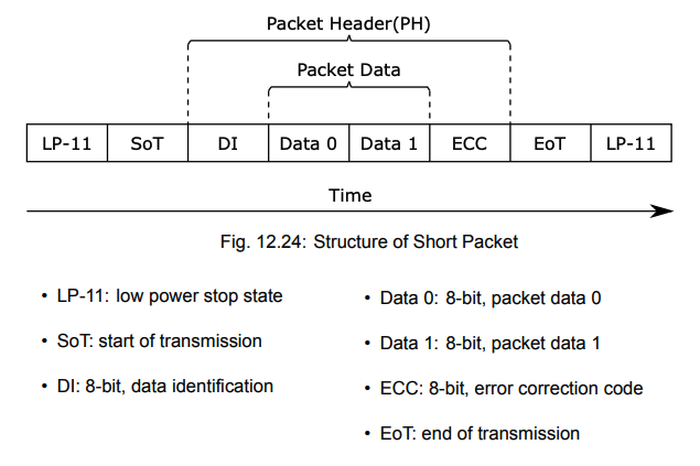
MIPI DSI Long Packet (Page 203)
Long Packet for MIPI DSI
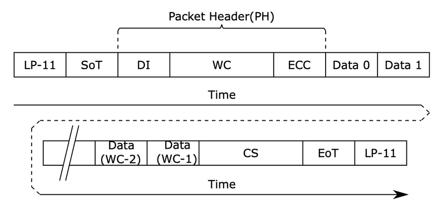
To send a command to the ST7703 LCD Controller, we'll transmit a MIPI DSI Long Packet in this format (pic above)...
Packet Header (4 bytes):
-
Data Identifier (DI) (1 byte):
Virtual Channel Identifier (Bits 6 to 7)
Data Type (Bits 0 to 5)
-
Word Count (WC) (2 bytes):
Number of bytes in the Packet Payload
-
Error Correction Code (ECC) (1 byte):
Allow single-bit errors to be corrected and 2-bit errors to be detected in the Packet Header
Packet Payload:
-
Data (0 to 65,541 bytes):
Number of data bytes should match the Word Count (WC)
Packet Footer:
-
Checksum (CS) (2 bytes):
16-bit Cyclic Redundancy Check (CCITT CRC)
Let's do this in Zig...
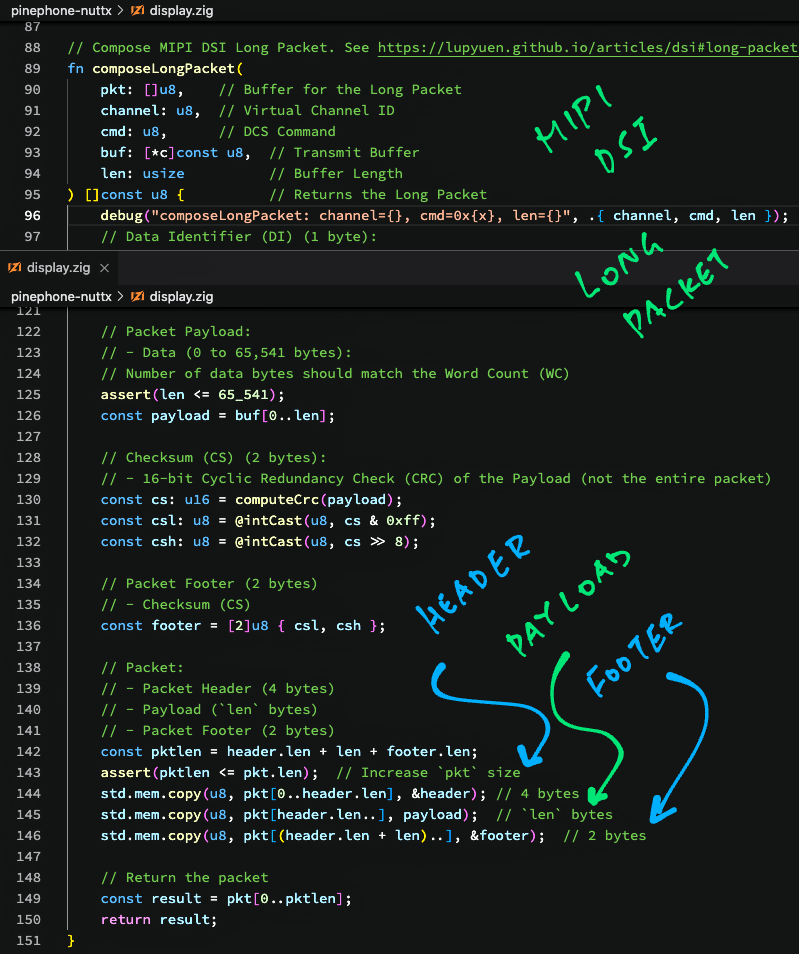
Compose Long Packet
This is our Zig Function that composes a Long Packet for MIPI Display Serial Interface: display.zig
// Compose MIPI DSI Long Packet.
// See https://lupyuen.github.io/articles/dsi#long-packet-for-mipi-dsi
fn composeLongPacket(
  pkt:     []u8,  // Buffer for the Returned Long Packet
  channel: u8,    // Virtual Channel ID
  cmd:     u8,    // DCS Command
  buf:     [*c]const u8,  // Transmit Buffer
  len:     usize          // Buffer Length
) []const u8 {  // Returns the Long Packet
  ...
(u8 in Zig is the same as uint8_t in C)
Our Zig Function composeLongPacket accepts the following parameters...
-
pkt: This is the buffer that we'll use to write the Long Packet and return it.It's declared as "
[]u8" which is a Slice of Bytes, roughly similar to "uint8_t[]" in C.(Except that the Buffer Size is also passed in the Slice)
channel: MIPI Display Serial Interface supports multiple Virtual Channels, we'll stick to Virtual Channel 0 for today-
cmd: Refers to the Display Command Set (DCS) that we'll send over the MIPI Display Serial Interface.For Long Packets, we'll send the DCS Long Write Command. (Which has Data Type
0x39)(Later we'll see the DCS Short Write Command)
-
buf: This is a C Pointer to the Transmit Buffer that will be packed inside the Long Packet. (As Packet Payload)It's declared as "
[*c]const u8", which is the same as "const uint8_t *" in C.("
[*c]" means that Zig will handle it as a C Pointer) len: Number of bytes in the Transmit Buffer
Our Zig Function composeLongPacket returns a Slice of Bytes that will contain the Long Packet.
(Declared as "[]const u8". Yep the returned Slice will be a Sub-Slice of pkt)
Why do we mix Slices and Pointers in the Parameters?
The parameters buf and len could have been passed as a Byte Slice in Zig...
Instead we're passing as an old-school C Pointer so that it's compatible with the C Interface for our function...
// (Eventual) C Interface for our function
ssize_t mipi_dsi_dcs_write(
  const struct device *dev,  // MIPI DSI Device
  uint8_t     channel,  // Virtual Channel ID
  uint8_t     cmd,      // DCS Command
  const void *buf,      // Transmit Buffer
  size_t      len       // Buffer Length
);
This C Interface is identical to the implementation of MIPI DSI in Zephyr OS. (See this)
Let's compose the Packet Header...
Packet Header
The Packet Header (4 bytes) of our Long Packet will contain...
-
Data Identifier (DI) (1 byte):
Virtual Channel Identifier (Bits 6 to 7)
Data Type (Bits 0 to 5)
(Data Type is the DCS Command)
-
Word Count (WC) (2 bytes):
Number of bytes in the Packet Payload
-
Error Correction Code (ECC) (1 byte):
Allow single-bit errors to be corrected and 2-bit errors to be detected in the Packet Header
This is how we compose the Packet Header: display.zig
  // Data Identifier (DI) (1 byte):
  // - Virtual Channel Identifier (Bits 6 to 7)
  // - Data Type (Bits 0 to 5)
  assert(channel < 4);
  assert(cmd < (1 << 6));
  const vc: u8 = channel;
  const dt: u8 = cmd;
  const di: u8 = (vc << 6) | dt;
First we populate the Data Indentifier (DI) with the Virtual Channel and DCS Command.
Then we convert the 16-bit Word Count (WC) to bytes...
  // Word Count (WC) (2 bytes):
  // Number of bytes in the Packet Payload
  const wc: u16 = @intCast(u16, len);
  const wcl: u8 = @intCast(u8, wc & 0xff);
  const wch: u8 = @intCast(u8, wc >> 8);
(@intCast will halt with a Runtime Panic if len is too big to be converted into a 16-bit unsigned integer u16)
Next comes the Error Correction Code (ECC). Which we compute based on the Data Identifier and Word Count...
  // Data Identifier + Word Count (3 bytes):
  // For computing Error Correction Code (ECC)
  const di_wc = [3]u8 { di, wcl, wch };

  // Compute Error Correction Code (ECC) for
  // Data Identifier + Word Count
  const ecc: u8 = computeEcc(di_wc);
("[3]u8" allocates a 3-byte array from the stack)
We'll cover computeEcc in a while.
Finally we pack everything into our 4-byte Packet Header...
  // Packet Header (4 bytes):
  // Data Identifier + Word Count + Error Correction Code
  const header = [4]u8 {
    di_wc[0],  // Data Identifier
    di_wc[1],  // Word Count (Low Byte)
    di_wc[2],  // Word Count (High Byte)
    ecc        // Error Correction Code
  };
Moving on to the Packet Payload...
Packet Payload
Remember that our Packet Payload is passed in as C-style buf (Buffer Pointer) and len (Buffer Length)?
This is how we convert the Packet Payload to a Byte Slice: display.zig
  // Packet Payload:
  // Data (0 to 65,541 bytes).
  // Number of data bytes should match the Word Count (WC)
  assert(len <= 65_541);

  // Convert to Byte Slice
  const payload = buf[0..len];
We'll concatenate the Packet Payload with the Header and Footer in a while.
(Packet Header and Footer are also Byte Slices)
From this code it's clear that a Zig Slice is nothing more than a Pointer and a Length... It's the tidier and safer way to pass buffers in Zig!
Packet Footer
At the end of our Long Packet is the Packet Footer: A 16-bit Cyclic Redundancy Check (CCITT CRC).
This is how we compute the CRC: display.zig
  // Checksum (CS) (2 bytes):
  // 16-bit Cyclic Redundancy Check (CRC) of the Payload
  // (not the entire packet)
  const cs: u16 = computeCrc(payload);
(computeCrc is explained in the Appendix)
The CRC goes into the 2-byte Packet Footer...
  // Convert CRC to 2 bytes
  const csl: u8 = @intCast(u8, cs & 0xff);
  const csh: u8 = @intCast(u8, cs >> 8);

  // Packet Footer (2 bytes):
  // Checksum (CS)
  const footer = [2]u8 { csl, csh };
Finally we're ready to put the Header, Payload and Footer together!
Combine Header, Payload and Footer
Our Long Packet will contain...
Packet Header (4 bytes)
Packet Payload (
lenbytes)Packet Footer (2 bytes)
Let's combine the Header, Payload and Footer: display.zig
  // Verify the Packet Buffer Length
  const pktlen = header.len + len + footer.len;
  assert(pktlen <= pkt.len);  // Increase `pkt` size if this fails

  // Copy Header to Packet Buffer
  std.mem.copy(
    u8,                  // Type
    pkt[0..header.len],  // Destination
    &header              // Source (4 bytes)
  );

  // Copy Payload to Packet Buffer
  // (After the Header)
  std.mem.copy(
    u8,                  // Type
    pkt[header.len..],   // Destination
    payload              // Source (`len` bytes)
  );

  // Copy Footer to Packet Buffer
  // (After the Payload)
  std.mem.copy(
    u8,                  // Type
    pkt[(header.len + len)..],  // Destination
    &footer              // Source (2 bytes)
  );
(std.mem.copy copies one Slice to another. It works like memcpy in C)
And we return the Byte Slice that contains our Long Packet, sized accordingly...
  // Return the packet
  const result = pkt[0..pktlen];
  return result;
}
That's how we compose a MIPI DSI Long Packet in Zig!
MIPI DSI Error Correction Code (Page 209)
Error Correction Code
Earlier we talked about computing the Error Correction Code (ECC) for the Packet Header...
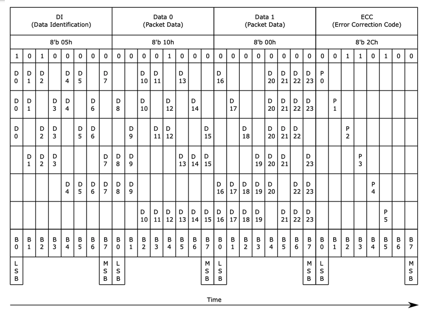
The 8-bit ECC shall be computed with this (magic) formula: (Page 209)
ECC[7] = 0
ECC[6] = 0
ECC[5] = D10^D11^D12^D13^D14^D15^D16^D17^D18^D19^D21^D22^D23
ECC[4] = D4^D5^D6^D7^D8^D9^D16^D17^D18^D19^D20^D22^D23
ECC[3] = D1^D2^D3^D7^D8^D9^D13^D14^D15^D19^D20^D21^D23
ECC[2] = D0^D2^D3^D5^D6^D9^D11^D12^D15^D18^D20^D21^D22
ECC[1] = D0^D1^D3^D4^D6^D8^D10^D12^D14^D17^D20^D21^D22^D23
ECC[0] = D0^D1^D2^D4^D5^D7^D10^D11^D13^D16^D20^D21^D22^D23
("^" means Exclusive OR)
(D0 to D23 refer to the pic above)
This is how we compute the ECC: display.zig
/// Compute the Error Correction Code (ECC) (1 byte):
/// Allow single-bit errors to be corrected and 2-bit errors to be detected in the Packet Header
/// See "12.3.6.12: Error Correction Code", Page 208 of BL808 Reference Manual:
/// https://files.pine64.org/doc/datasheet/ox64/BL808_RM_en_1.0(open).pdf
fn computeEcc(
  di_wc: [3]u8  // Data Identifier + Word Count (3 bytes)
) u8 {
  ...
Our Zig Function computeEcc accepts a 3-byte array, containing the first 3 bytes of the Packet Header.
("[3]u8" is equivalent to "uint8_t[3]" in C)
We combine the 3 bytes into a 24-bit word...
  // Combine DI and WC into a 24-bit word
  var di_wc_word: u32 =
    di_wc[0]
    | (@intCast(u32, di_wc[1]) << 8)
    | (@intCast(u32, di_wc[2]) << 16);
Then we extract the 24 bits into d[0] to d[23]...
  // Allocate an array of 24 bits from the stack,
  // initialised to zeros
  var d = std.mem.zeroes([24]u1);

  // Extract the 24 bits from the word
  var i: usize = 0;
  while (i < 24) : (i += 1) {
    d[i] = @intCast(u1, di_wc_word & 1);
    di_wc_word >>= 1;
  }
(std.mem.zeroes allocates an array from the stack, initialised to zeroes)
Note that we're working with Bit Values...
"
u1" represents a Single Bit Value"
[24]u1" is an Array of 24 Bits
We compute the ECC Bits according to the Magic Formula...
  // Allocate an array of 8 bits from the stack,
  // initialised to zeros
  var ecc = std.mem.zeroes([8]u1);

  // Compute the ECC bits
  ecc[7] = 0;
  ecc[6] = 0;
  ecc[5] = d[10] ^ d[11] ^ d[12] ^ d[13] ^ d[14] ^ d[15] ^ d[16] ^ d[17] ^ d[18] ^ d[19] ^ d[21] ^ d[22] ^ d[23];
  ecc[4] = d[4]  ^ d[5]  ^ d[6]  ^ d[7]  ^ d[8]  ^ d[9]  ^ d[16] ^ d[17] ^ d[18] ^ d[19] ^ d[20] ^ d[22] ^ d[23];
  ecc[3] = d[1]  ^ d[2]  ^ d[3]  ^ d[7]  ^ d[8]  ^ d[9]  ^ d[13] ^ d[14] ^ d[15] ^ d[19] ^ d[20] ^ d[21] ^ d[23];
  ecc[2] = d[0]  ^ d[2]  ^ d[3]  ^ d[5]  ^ d[6]  ^ d[9]  ^ d[11] ^ d[12] ^ d[15] ^ d[18] ^ d[20] ^ d[21] ^ d[22];
  ecc[1] = d[0]  ^ d[1]  ^ d[3]  ^ d[4]  ^ d[6]  ^ d[8]  ^ d[10] ^ d[12] ^ d[14] ^ d[17] ^ d[20] ^ d[21] ^ d[22] ^ d[23];
  ecc[0] = d[0]  ^ d[1]  ^ d[2]  ^ d[4]  ^ d[5]  ^ d[7]  ^ d[10] ^ d[11] ^ d[13] ^ d[16] ^ d[20] ^ d[21] ^ d[22] ^ d[23];
Finally we merge the ECC Bits into a single byte and return it...
  // Merge the ECC bits
  return @intCast(u8, ecc[0])
    | (@intCast(u8, ecc[1]) << 1)
    | (@intCast(u8, ecc[2]) << 2)
    | (@intCast(u8, ecc[3]) << 3)
    | (@intCast(u8, ecc[4]) << 4)
    | (@intCast(u8, ecc[5]) << 5)
    | (@intCast(u8, ecc[6]) << 6)
    | (@intCast(u8, ecc[7]) << 7);
}
And we're done with the Error Correction Code!
MIPI DSI Short Packet (Page 201)
Compose Short Packet
We've seen the Long Packet. Is there a Short Packet?
Yep! If we're transmitting 1 or 2 bytes to the ST7703 LCD Controller, we may send a MIPI DSI Short Packet (pic above)...
A MIPI DSI Short Packet (compared with Long Packet)...
Doesn't have Packet Payload and Packet Footer (CRC)
Instead of Word Count (WC), the Packet Header now has 2 bytes of data
-
DCS Command (Data Type) is...
DCS Short Write Without Parameter (
0x05) for sending 1 byte of dataDCS Short Write With Parameter (
0x15) for sending 2 bytes of data Everything else is the same
This is how we compose a Short Packet: display.zig
// Compose MIPI DSI Short Packet.
// See https://lupyuen.github.io/articles/dsi#appendix-short-packet-for-mipi-dsi
fn composeShortPacket(
  pkt:     []u8,    // Buffer for the Returned Short Packet
  channel: u8,      // Virtual Channel ID
  cmd:     u8,      // DCS Command
  buf:     [*c]const u8,  // Transmit Buffer
  len:     usize          // Buffer Length
) []const u8 {  // Returns the Short Packet

  // Short Packet can only have 1 or 2 data bytes
  assert(len == 1 or len == 2);
composeShortPacket accepts the same parameters as composeLongPacket.
We populate Data Indentifier (DI) the same way, with Virtual Channel and DCS Command...
  // Data Identifier (DI) (1 byte):
  // - Virtual Channel Identifier (Bits 6 to 7)
  // - Data Type (Bits 0 to 5)
  assert(channel < 4);
  assert(cmd < (1 << 6));
  const vc: u8 = channel;
  const dt: u8 = cmd;
  const di: u8 = (vc << 6) | dt;
Our Packet Header will include two bytes of data...
  // Data (2 bytes), fill with 0
  // if Second Byte is missing
  const data = [2]u8 {
    buf[0],                       // First Data Byte
    if (len == 2) buf[1] else 0,  // Second Data Byte
  };
We compute the Error Correction Code (ECC) based on the Data Identifier and the two Data Bytes...
  // Data Identifier + Data (3 bytes):
  // For computing Error Correction Code (ECC)
  const di_data = [3]u8 {
    di,       // Data Identifier
    data[0],  // First Data Byte
    data[1]   // Second Data Byte
  };

  // Compute Error Correction Code (ECC)
  // for Data Identifier + Word Count
  const ecc: u8 = computeEcc(di_data);
(computeEcc is explained here)
We pack everything into our 4-byte Packet Header...
  // Packet Header (4 bytes):
  // Data Identifier + Data + Error Correction Code
  const header = [4]u8 {
    di_data[0],  // Data Identifier
    di_data[1],  // First Data Byte
    di_data[2],  // Second Data Byte
    ecc          // Error Correction Code
  };
We copy the Packet Header into our Packet Buffer...
  // Verify the Packet Buffer Length
  const pktlen = header.len;
  assert(pktlen <= pkt.len);  // Increase `pkt` size

  // Copy Header to Packet Buffer
  std.mem.copy(
    u8,                  // Type
    pkt[0..header.len],  // Destination
    &header              // Source (4 bytes)
  );
And we return the Byte Slice that contains our Short Packet, sized accordingly...
  // Return the packet
  const result = pkt[0..pktlen];
  return result;
}
We're done with Long and Short Packets for MIPI DSI, let's test them...
Test MIPI DSI Driver
How will we know if our Long and Short Packets are created correctly?
Let's write a Test Case to verify that our MIPI DSI Packets are constructed correctly: display.zig
// Test Compose Short Packet (With Parameter)
const short_pkt_param = [_]u8 {
  0xbc, 0x4e,
};
We'll compose a Short Packet that will pack the 2 bytes above.
(We write "[_]u8" to declare a Byte Array in Zig)
First we allocate a Packet Buffer from the Stack, initialised to zeroes...
// Allocate Packet Buffer of 128 bytes
var pkt_buf = std.mem.zeroes([128]u8);
("[128]u8" is equivalent to "uint8_t[128]" in C)
Then we call composeShortPacket to construct the Short Packet...
// Compose a Short Packet (With Parameter)
const short_pkt_param_result = composeShortPacket(
  &pkt_buf,  //  Packet Buffer
  0,         //  Virtual Channel
  MIPI_DSI_DCS_SHORT_WRITE_PARAM, // DCS Command: 0x15
  &short_pkt_param,    // Transmit Buffer
  short_pkt_param.len  // Buffer Length
);
We dump the contents of the returned packet...
// Dump the Returned Packet
debug("Result:", .{});
dump_buffer(
  &short_pkt_param_result[0],  // Pointer to Packet
  short_pkt_param_result.len   // Length of Packet
);
(We'll talk about dump_buffer in a while)
Finally we verify that the result is "15 BC 4E 35"...
//  Verify the Returned Packet
assert(
  std.mem.eql(  // Compare 2 Slices...
    u8,         // Slice Type
    short_pkt_param_result,   // First Slice
    &[_]u8 {                  // Second Slice
      0x15, 0xbc, 0x4e, 0x35  // Expected Data
    }
  )
);
(std.mem.eql returns True if the two Slices are identical)
The above Test Case shows this output...
Testing Compose Short Packet (With Parameter)...
composeShortPacket:
  channel=0, cmd=0x15, len=2
Result:
  15 bc 4e 35
In the next chapter we'll learn to run the Test Case on the QEMU Emulator for Arm64.
What's dump_buffer?
dump_buffer is a C Function that dumps a packet to the console. We imported the C Function into Zig like so: display.zig
/// Import `dump_buffer` Function from C
extern fn dump_buffer(
  data: [*c]const u8,  // C Pointer to Packet
  len: usize           // Length of Packet
) void;                // No Return Value
dump_buffer is defined here: hello_main.c
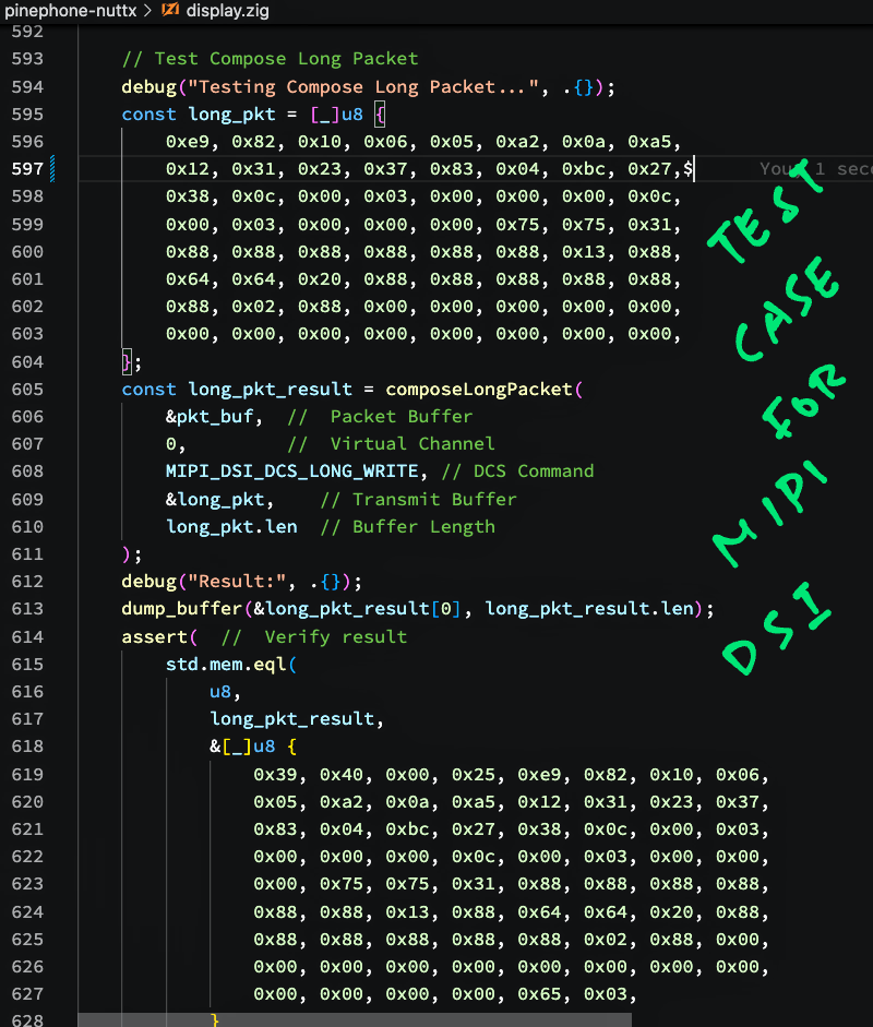
What about testing Long Packets?
We have 3 Test Cases for testing the creation of Long and Short Packets...
How did we get the Expected Result for our Test Cases?
We ran the p-boot Display Code (in C) on Apache NuttX RTOS and captured the Expected Packet Contents.
So we can be sure that our Zig Code will produce the same results as the (poorly documented) C Version.
Let's find out how we ran the Test Cases on QEMU Emulator...
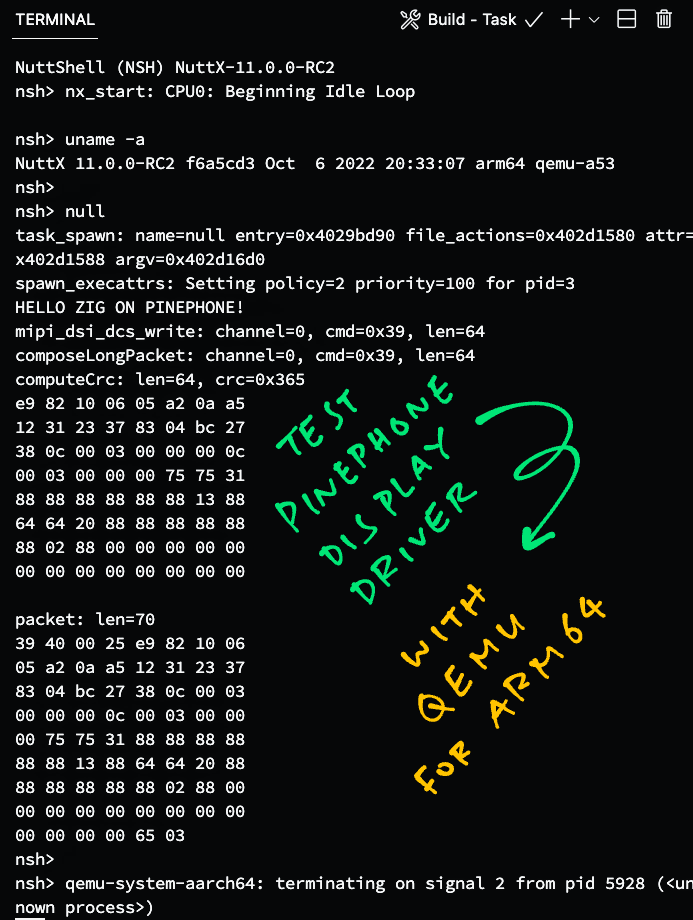
Run MIPI DSI Driver on QEMU
Can we test our MIPI DSI code on Apache NuttX RTOS... Without a PinePhone?
Yep! Let's test our Zig code on the QEMU Emulator for Arm64, running Apache NuttX RTOS.
Follow these steps to build NuttX RTOS for QEMU Arm64...
Then we compile our Zig App (display.zig) and link it with NuttX...
##  Download the Zig App
git clone --recursive https://github.com/lupyuen/pinephone-nuttx
cd pinephone-nuttx

##  Compile the Zig App for PinePhone
##  (armv8-a with cortex-a53)
##  TODO: Change "$HOME/nuttx" to your NuttX Project Directory
zig build-obj \
  -target aarch64-freestanding-none \
  -mcpu cortex_a53 \
  -isystem "$HOME/nuttx/nuttx/include" \
  -I "$HOME/nuttx/apps/include" \
  display.zig

##  Copy the compiled app to NuttX and overwrite `null.o`
##  TODO: Change "$HOME/nuttx" to your NuttX Project Directory
cp display.o \
  $HOME/nuttx/apps/examples/null/*null.o

##  Build NuttX to link the Zig Object from `null.o`
##  TODO: Change "$HOME/nuttx" to your NuttX Project Directory
cd $HOME/nuttx/nuttx
make
(We copied the Zig Compiler Options from GCC)
We start QEMU to boot NuttX...
## Run GIC v2 with QEMU
qemu-system-aarch64 \
  -smp 4 \
  -cpu cortex-a53 \
  -nographic \
  -machine virt,virtualization=on,gic-version=2 \
  -net none \
  -chardev stdio,id=con,mux=on \
  -serial chardev:con \
  -mon chardev=con,mode=readline \
  -kernel ./nuttx
(We chose GIC Version 2 to be consistent with PinePhone)
At the NuttX Shell, enter this command to run our Zig Test Cases...
null
Our Test Cases for Long and Short Packets should complete without Assertion Failures...
NuttShell (NSH) NuttX-11.0.0-RC2
nsh> null
HELLO ZIG ON PINEPHONE!
Testing Compose Short Packet (Without Parameter)...
composeShortPacket: channel=0, cmd=0x5, len=1
Result:
05 11 00 36
Testing Compose Short Packet (With Parameter)...
composeShortPacket: channel=0, cmd=0x15, len=2
Result:
15 bc 4e 35
Testing Compose Long Packet...
composeLongPacket: channel=0, cmd=0x39, len=64
Result:
39 40 00 25 e9 82 10 06
05 a2 0a a5 12 31 23 37
83 04 bc 27 38 0c 00 03
00 00 00 0c 00 03 00 00
00 75 75 31 88 88 88 88
88 88 13 88 64 64 20 88
88 88 88 88 88 02 88 00
00 00 00 00 00 00 00 00
00 00 00 00 65 03
nsh>
Yep we have successfully tested our MIPI DSI Code on NuttX RTOS and QEMU Arm64!

Initialise ST7703 LCD Controller
But our MIPI DSI Driver hasn't talked to the PinePhone Display!
Here comes the tougher (and poorly documented) part... Accessing the Hardware Registers of the Allwinner A64 SoC. So that we can send MIPI DSI Packets to PinePhone's Display.
Before that, let's prepare the MIPI DSI Packets (Long and Short) that we'll send to the display...
Earlier we talked about the 20 Initialisation Commands that our Zig Driver will send to the ST7703 LCD Controller (over MIPI DSI)...
This is how we send the 20 commands: display.zig
/// Initialise the ST7703 LCD Controller in Xingbangda XBD599 LCD Panel.
/// See https://lupyuen.github.io/articles/dsi#initialise-lcd-controller
pub export fn nuttx_panel_init() void {

  // Most of these commands are documented in the ST7703 Datasheet:
  // https://files.pine64.org/doc/datasheet/pinephone/ST7703_DS_v01_20160128.pdf

  // Command #1
  writeDcs(&[_]u8 {
    0xB9,  // SETEXTC (Page 131): Enable USER Command
    0xF1,  // Enable User command
    0x12,  // (Continued)
    0x83   // (Continued)
  });

  // Omitted: Commands #2 to #19
  ...

  // Wait 120 milliseconds
  _ = c.usleep(120 * 1000);

  // Command #20
  writeDcs(&[_]u8 {
    0x29  // Display On (Page 97): Recover from DISPLAY OFF mode (MIPI_DCS_SET_DISPLAY_ON)
  });
}
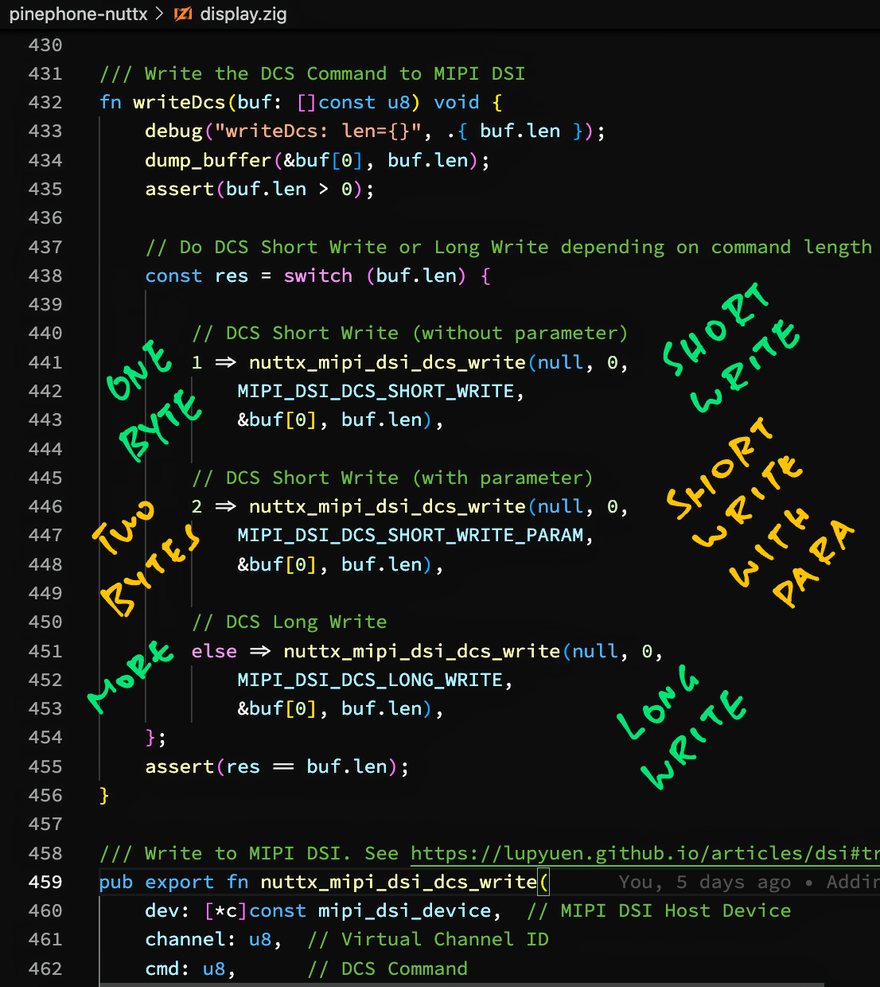
To send a command to ST7703 Controller, writeDcs executes a DCS Short Write or DCS Long Write over MIPI DSI, depending on the length of the command: display.zig
/// Write the DCS Command to MIPI DSI
fn writeDcs(buf: []const u8) void {

  // Do DCS Short Write or Long Write depending on command length
  assert(buf.len > 0);
  const res = switch (buf.len) {

    // If Command Length is 1:
    // DCS Short Write (without parameter)
    1 => nuttx_mipi_dsi_dcs_write(null, 0,
      MIPI_DSI_DCS_SHORT_WRITE,
      &buf[0], buf.len),

    // If Command Length is 2:
    // DCS Short Write (with parameter)
    2 => nuttx_mipi_dsi_dcs_write(null, 0,
      MIPI_DSI_DCS_SHORT_WRITE_PARAM,
      &buf[0], buf.len),

    // If Command Length is 3 or longer:
    // DCS Long Write
    else => nuttx_mipi_dsi_dcs_write(null, 0,
      MIPI_DSI_DCS_LONG_WRITE,
      &buf[0], buf.len),
  };
  assert(res == buf.len);
}
(We write "&buf[0]" to convert a Slice into a Pointer)
Let's study our Zig Function that sends Long Packets and Short Packets over MIPI DSI: nuttx_mipi_dsi_dcs_write...
Send MIPI DSI Packet
Finally we're ready to access the Hardware Registers of PinePhone's Allwinner A64 SoC, to send MIPI DSI Packets to the display.
We'll call these Zig Functions to manipulate A64's Hardware Registers...
-
getreg32: Read the Value of the Hardware Register at the specified Address
fn getreg32(addr: u64) u32 -
putreg32: Set the Value of the Hardware Register at the specified Address
fn putreg32(val: u32, addr: u64)(Note that the Value comes before the Address)
-
modifyreg32: Clear and set the bits of the Hardware Register at the Address
fn modifyreg32(
  addr: u64,       // Address to modify
  clearbits: u32,  // Bits to clear, like (1 << bit)
  setbits: u32     // Bit to set, like (1 << bit)
)
This is how we send MIPI DSI Packets to PinePhone's Display: display.zig
/// Write Packet to MIPI DSI. See https://lupyuen.github.io/articles/dsi#transmit-packet-over-mipi-dsi
pub export fn nuttx_mipi_dsi_dcs_write(
  dev:     [*c]const mipi_dsi_device,  // MIPI DSI Host Device
  channel: u8,  // Virtual Channel ID
  cmd:     u8,  // DCS Command
  buf:     [*c]const u8,  // Transmit Buffer
  len:     usize          // Buffer Length
) isize {  // On Success: Return number of written bytes. On Error: Return negative error code
  ...
Our function accepts a DCS Long Write or DCS Short Write command. (Depending on the packet size)
Based on the DCS Command received, we compose a Long Packet or Short Packet...
  // Allocate Packet Buffer
  var pkt_buf = std.mem.zeroes([128]u8);

  // Compose Short or Long Packet depending on DCS Command
  const pkt = switch (cmd) {

    // For DCS Long Write: Compose Long Packet
    MIPI_DSI_DCS_LONG_WRITE =>
      composeLongPacket(&pkt_buf, channel, cmd, buf, len),

    // For DCS Short Write (with and without parameter):
    // Compose Short Packet
    MIPI_DSI_DCS_SHORT_WRITE,
    MIPI_DSI_DCS_SHORT_WRITE_PARAM =>
      composeShortPacket(&pkt_buf, channel, cmd, buf, len),

    // DCS Command not supported
    else => unreachable,
  };
(composeLongPacket is explained here)
(composeShortPacket is explained here)
To prepare for Packet Transmission, we initialise the A64 Hardware Register DSI_CMD_CTL_REG (DSI Low Power Control Register)...
  // Set the following bits to 1 in DSI_CMD_CTL_REG (DSI Low Power Control Register) at Offset 0x200:
  // RX_Overflow (Bit 26): Clear flag for "Receive Overflow"
  // RX_Flag (Bit 25): Clear flag for "Receive has started"
  // TX_Flag (Bit 9): Clear flag for "Transmit has started"
  // All other bits must be set to 0.
  const DSI_CMD_CTL_REG = DSI_BASE_ADDRESS + 0x200;
  const RX_Overflow = 1 << 26;
  const RX_Flag     = 1 << 25;
  const TX_Flag     = 1 << 9;
  putreg32(
    RX_Overflow | RX_Flag | TX_Flag,
    DSI_CMD_CTL_REG
  );
(DSI_CMD_CTL_REG is explained here)
Next we write the Long or Short Packet to DSI_CMD_TX_REG (DSI Low Power Transmit Package Register) in 4-byte chunks...
  // Write the Long Packet to DSI_CMD_TX_REG
  // (DSI Low Power Transmit Package Register) at Offset 0x300 to 0x3FC
  const DSI_CMD_TX_REG = DSI_BASE_ADDRESS + 0x300;
  var addr: u64 = DSI_CMD_TX_REG;
  var i: usize = 0;
  while (i < pkt.len) : (i += 4) {
    // Fetch the next 4 bytes, fill with 0 if not available
    const b = [4]u32 {
      pkt[i],
      if (i + 1 < pkt.len) pkt[i + 1] else 0,
      if (i + 2 < pkt.len) pkt[i + 2] else 0,
      if (i + 3 < pkt.len) pkt[i + 3] else 0,
    };

    // Merge the next 4 bytes into a 32-bit value
    const v: u32 =
      b[0]
      + (b[1] << 8)
      + (b[2] << 16)
      + (b[3] << 24);

    // Write the 32-bit value
    assert(addr <= DSI_BASE_ADDRESS + 0x3FC);
    modifyreg32(addr, 0xFFFF_FFFF, v);
    addr += 4;
  }
(DSI_CMD_TX_REG is explained here)
We set the Packet Length in DSI_CMD_CTL_REG (DSI Low Power Control Register)...
  // Set Packet Length - 1 in Bits 0 to 7 (TX_Size) of
  // DSI_CMD_CTL_REG (DSI Low Power Control Register) at Offset 0x200
  modifyreg32(DSI_CMD_CTL_REG, 0xFF, @intCast(u32, pkt.len) - 1);
(DSI_CMD_CTL_REG is explained here)
We begin MIPI DSI Low Power Transmission by writing to DSI_INST_JUMP_SEL_REG...
  // Set DSI_INST_JUMP_SEL_REG (Offset 0x48, undocumented)
  // to begin the Low Power Transmission (LPTX)
  const DSI_INST_JUMP_SEL_REG = DSI_BASE_ADDRESS + 0x48;
  const DSI_INST_ID_LPDT = 4;
  const DSI_INST_ID_LP11 = 0;
  const DSI_INST_ID_END  = 15;
  putreg32(
    DSI_INST_ID_LPDT << (4 * DSI_INST_ID_LP11) |
    DSI_INST_ID_END  << (4 * DSI_INST_ID_LPDT),
    DSI_INST_JUMP_SEL_REG
  );
(DSI_INST_JUMP_SEL_REG is explained here)
Our MIPI DSI Packet gets transmitted when we toggle the DSI Processing State...
  // Disable DSI Processing then Enable DSI Processing
  disableDsiProcessing();
  enableDsiProcessing();
(disableDsiProcessing is defined here)
(enableDsiProcessing is defined here)
We must wait for the Packet Transmission to complete...
  // Wait for transmission to complete
  const res = waitForTransmit();
  if (res < 0) {
    disableDsiProcessing();
    return res;
  }

  // Return number of written bytes
  return @intCast(isize, len);
}
(waitForTransmit is defined here)
And we're done transmitting a MIPI DSI Packet to PinePhone's Display!
Test MIPI DSI Driver on PinePhone
Are we sure that our Zig Driver talks OK to PinePhone's MIPI DSI Display?
Our Zig Driver sends 20 commands over MIPI DSI to initialise PinePhone's Display...
Let's test it with Apache NuttX RTOS on PinePhone!
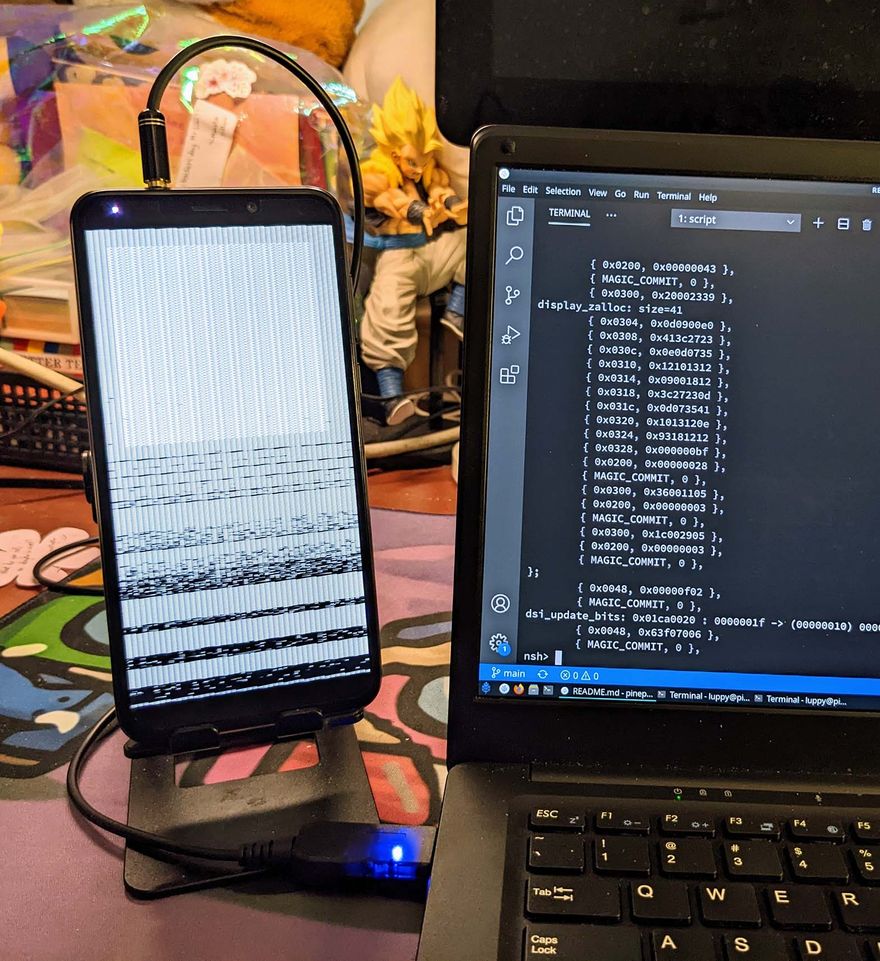
This p-boot Display Code (in C) renders a "Test Pattern" (pic above) on PinePhone's Display...
Inside the above code is the C Function panel_init that sends the 20 commands to initialise PinePhone's Display...
We modify panel_init so that it calls our Zig Driver instead...
// p-boot calls this to init ST7703
static void panel_init(void) {
  // We call Zig Driver to init ST7703
  nuttx_panel_init();
}
(nuttx_panel_init is explained here)
(p-boot Display Code modified for Zig)
Follow these steps to build Apache NuttX RTOS and our Zig Display Driver...
Boot PinePhone with NuttX RTOS in the microSD Card.
At the NuttX Shell, enter this command to test our Zig Display Driver...
hello
We should see our Zig Driver composing the MIPI DSI Packets and setting the Hardware Registers of the Allwinner A64 SoC...
HELLO NUTTX ON PINEPHONE!
...
Shell (NSH) NuttX-11.0.0-RC2
nsh> hello
...
writeDcs: len=4
b9 f1 12 83
mipi_dsi_dcs_write: channel=0, cmd=0x39, len=4
composeLongPacket: channel=0, cmd=0x39, len=4
packet: len=10
39 04 00 2c b9 f1 12 83
84 5d
modifyreg32: addr=0x300, val=0x2c000439
modifyreg32: addr=0x304, val=0x8312f1b9
modifyreg32: addr=0x308, val=0x00005d84
modifyreg32: addr=0x200, val=0x00000009
modifyreg32: addr=0x010, val=0x00000000
modifyreg32: addr=0x010, val=0x00000001
...
Our Zig Display Driver powers on the PinePhone Display and renders the Test Pattern... Exactly like the earlier code in C! 🎉
Are we really sure that our Zig Driver works OK?
100% Yep! If our Zig Driver didn't send the ST7703 Commands correctly, PinePhone's Display would stay dark.
Our PinePhone Display Driver in Zig has successfully...
Sent 20 MIPI DSI Commands to initialise PinePhone's ST7703 LCD Controller
With the correct MIPI DSI Long Packets and Short Packets
By accessing the correct Hardware Registers in PinePhone's Allwinner A64 SoC
But we haven't actually rendered any graphics to the display yet...
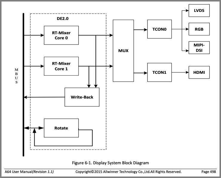
Display Engine (DE) and Timing Controller (TCON0) from A64 User Manual (Page 498)
Render Graphics on PinePhone Display
Can our driver render graphics on the PinePhone Display?
Sadly our PinePhone Display Driver isn't complete... Rendering graphics on PinePhone's Display isn't done with MIPI DSI Packets.
Instead we shall program these two controllers in PinePhone's Allwinner A64 SoC...
-
Display Engine (DE): Execute the Rendering Pipeline to generate the pixels for display
(Handles image buffering, scaling, mixing, ...)
-
Timing Controller (TCON0): Pump the generated pixels at the right clock frequency to the MIPI DSI display
(Pic above)
Why won't PinePhone's Display accept MIPI DSI Packets for graphics?
PinePhone's ST7703 LCD Controller doesn't have any RAM inside...
Thus we need to pump a constant stream of pixels to the display. Which won't work with MIPI DSI Packets. (Because it's too inefficient)
A64's Display Engine (DE) and Timing Controller (TCON0) were created to blast the pixels efficiently from PinePhone's RAM to the ST7703 LCD Controller.
(All fully automated, no interrupts needed!)
We'll talk about DE and TCON0 in the next article.
The PinePhone Display Driver that we're building... What interface will it expose?
Our PinePhone Display Driver (in C or Zig) shall expose the standard Display Driver Interface that's expected by Apache NuttX RTOS.
Here's the implementation of the Display Driver Interface for the Sitronix ST7789 LCD Controller...
What's Next
Today we've seen the Zig Internals of our new PinePhone Display Driver for Apache NuttX RTOS. I hope that coding the driver in Zig has made it a little easier to understand what's inside.
Some parts of the driver were simpler to code in Zig than in C. I'm glad I chose Zig for the driver!
(I took longer to write this article... Than to code the Zig Driver!)
In the next article we shall implement the rendering features of the PinePhone Display Driver.
There's plenty to be done for NuttX on PinePhone, please lemme know if you would like to join me 🙏
Check out the other articles on NuttX RTOS for PinePhone...
Many Thanks to my GitHub Sponsors for supporting my work! This article wouldn't have been possible without your support.
Got a question, comment or suggestion? Create an Issue or submit a Pull Request here...
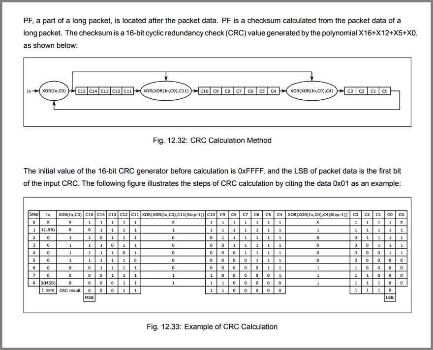
MIPI DSI Cyclic Redundancy Check (Page 210)
Appendix: Cyclic Redundancy Check
Earlier we talked about computing the 16-bit Cyclic Redundancy Check (CCITT CRC) for the MIPI DSI Packet Footer (pic above)...
This is how our Zig Driver computes the CCITT CRC: display.zig
/// Compute 16-bit Cyclic Redundancy Check (CRC).
/// See "12.3.6.13: Packet Footer", Page 210 of BL808 Reference Manual:
/// https://files.pine64.org/doc/datasheet/ox64/BL808_RM_en_1.0(open).pdf
fn computeCrc(
  data: []const u8
) u16 {
  // Use CRC-16-CCITT (x^16 + x^12 + x^5 + 1)
  const crc = crc16ccitt(data, 0xffff);
  return crc;
}

/// Return a 16-bit CRC-CCITT of the contents of the `src` buffer.
/// Based on https://github.com/lupyuen/incubator-nuttx/blob/pinephone/libs/libc/misc/lib_crc16.c
fn crc16ccitt(src: []const u8, crc16val: u16) u16 {
  var i: usize = 0;
  var v = crc16val;
  while (i < src.len) : (i += 1) {
    v = (v >> 8)
      ^ crc16ccitt_tab[(v ^ src[i]) & 0xff];
  }
  return v;
}
crc16ccitt_tab is the standard table for computing CRC-16-CCITT based on the polynomial "x^16 + x^12 + x^5 + 1"...
/// From CRC-16-CCITT (x^16 + x^12 + x^5 + 1)
const crc16ccitt_tab = [256]u16 {
  0x0000, 0x1189, 0x2312, 0x329b, 0x4624, 0x57ad, 0x6536, 0x74bf,
  0x8c48, 0x9dc1, 0xaf5a, 0xbed3, 0xca6c, 0xdbe5, 0xe97e, 0xf8f7,
  0x1081, 0x0108, 0x3393, 0x221a, 0x56a5, 0x472c, 0x75b7, 0x643e,
  0x9cc9, 0x8d40, 0xbfdb, 0xae52, 0xdaed, 0xcb64, 0xf9ff, 0xe876,
  0x2102, 0x308b, 0x0210, 0x1399, 0x6726, 0x76af, 0x4434, 0x55bd,
  0xad4a, 0xbcc3, 0x8e58, 0x9fd1, 0xeb6e, 0xfae7, 0xc87c, 0xd9f5,
  0x3183, 0x200a, 0x1291, 0x0318, 0x77a7, 0x662e, 0x54b5, 0x453c,
  0xbdcb, 0xac42, 0x9ed9, 0x8f50, 0xfbef, 0xea66, 0xd8fd, 0xc974,
  0x4204, 0x538d, 0x6116, 0x709f, 0x0420, 0x15a9, 0x2732, 0x36bb,
  0xce4c, 0xdfc5, 0xed5e, 0xfcd7, 0x8868, 0x99e1, 0xab7a, 0xbaf3,
  0x5285, 0x430c, 0x7197, 0x601e, 0x14a1, 0x0528, 0x37b3, 0x263a,
  0xdecd, 0xcf44, 0xfddf, 0xec56, 0x98e9, 0x8960, 0xbbfb, 0xaa72,
  0x6306, 0x728f, 0x4014, 0x519d, 0x2522, 0x34ab, 0x0630, 0x17b9,
  0xef4e, 0xfec7, 0xcc5c, 0xddd5, 0xa96a, 0xb8e3, 0x8a78, 0x9bf1,
  0x7387, 0x620e, 0x5095, 0x411c, 0x35a3, 0x242a, 0x16b1, 0x0738,
  0xffcf, 0xee46, 0xdcdd, 0xcd54, 0xb9eb, 0xa862, 0x9af9, 0x8b70,
  0x8408, 0x9581, 0xa71a, 0xb693, 0xc22c, 0xd3a5, 0xe13e, 0xf0b7,
  0x0840, 0x19c9, 0x2b52, 0x3adb, 0x4e64, 0x5fed, 0x6d76, 0x7cff,
  0x9489, 0x8500, 0xb79b, 0xa612, 0xd2ad, 0xc324, 0xf1bf, 0xe036,
  0x18c1, 0x0948, 0x3bd3, 0x2a5a, 0x5ee5, 0x4f6c, 0x7df7, 0x6c7e,
  0xa50a, 0xb483, 0x8618, 0x9791, 0xe32e, 0xf2a7, 0xc03c, 0xd1b5,
  0x2942, 0x38cb, 0x0a50, 0x1bd9, 0x6f66, 0x7eef, 0x4c74, 0x5dfd,
  0xb58b, 0xa402, 0x9699, 0x8710, 0xf3af, 0xe226, 0xd0bd, 0xc134,
  0x39c3, 0x284a, 0x1ad1, 0x0b58, 0x7fe7, 0x6e6e, 0x5cf5, 0x4d7c,
  0xc60c, 0xd785, 0xe51e, 0xf497, 0x8028, 0x91a1, 0xa33a, 0xb2b3,
  0x4a44, 0x5bcd, 0x6956, 0x78df, 0x0c60, 0x1de9, 0x2f72, 0x3efb,
  0xd68d, 0xc704, 0xf59f, 0xe416, 0x90a9, 0x8120, 0xb3bb, 0xa232,
  0x5ac5, 0x4b4c, 0x79d7, 0x685e, 0x1ce1, 0x0d68, 0x3ff3, 0x2e7a,
  0xe70e, 0xf687, 0xc41c, 0xd595, 0xa12a, 0xb0a3, 0x8238, 0x93b1,
  0x6b46, 0x7acf, 0x4854, 0x59dd, 0x2d62, 0x3ceb, 0x0e70, 0x1ff9,
  0xf78f, 0xe606, 0xd49d, 0xc514, 0xb1ab, 0xa022, 0x92b9, 0x8330,
  0x7bc7, 0x6a4e, 0x58d5, 0x495c, 0x3de3, 0x2c6a, 0x1ef1, 0x0f78,
};


Latest comments (1)
OUHHHHHAAAAAAA