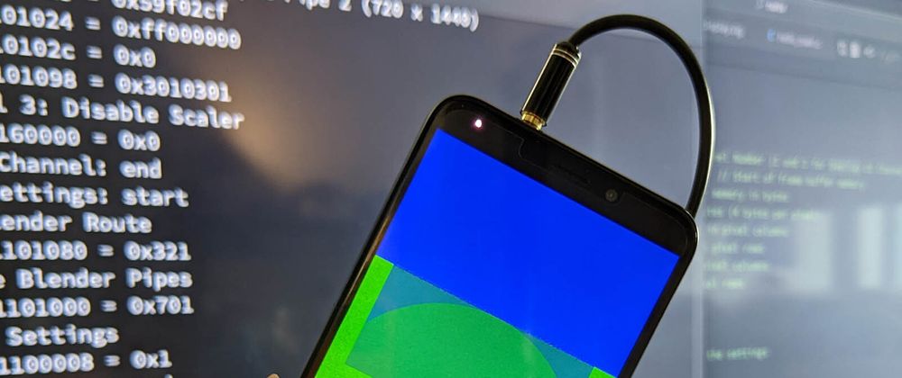
Pine64 PinePhone (pic above) will soon support the rendering of graphics on the LCD Display... When we boot the official release of Apache NuttX RTOS!
We're building the NuttX Display Driver for PinePhone in small chunks, starting with the driver for MIPI Display Serial Interface.
In this article we'll learn...
What's needed to create a Complete Display Driver for PinePhone
How our driver for MIPI Display Serial Interface fits into the grand plan
How we're building the missing pieces of the PinePhone Display Driver
Why most of the Display Driver is in the Zig Programming Language
Let's continue the (super looong) journey from our NuttX Porting Journal...
Complete Display Driver for PinePhone
NuttX will render graphics on PinePhone's LCD Display...
What's inside the Display Driver for PinePhone?
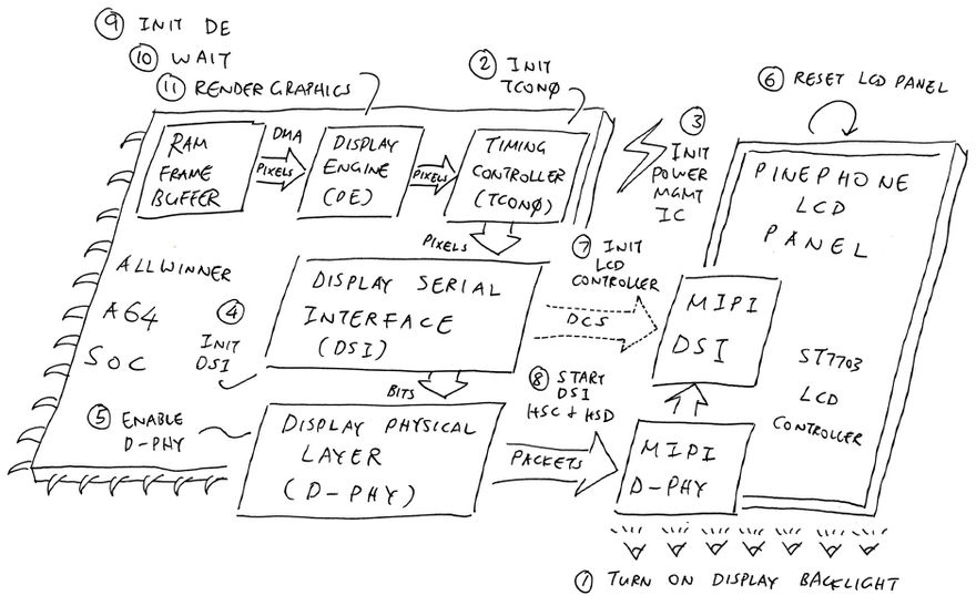
Through Reverse Engineering (and plenty of experimenting), we discovered that these steps are needed to create a Complete Display Driver for PinePhone (pic above)...
-
Turn on PinePhone's Display Backlight
(Through Programmable I/O and Pulse-Width Modulation)
-
Initialise Allwinner A64's Timing Controller (TCON0)
(Which will pump pixels continuously to the LCD Display)
-
Initialise PinePhone's Power Management Integrated Circuit (PMIC)
(To power on PinePhone's LCD Panel)
-
Enable Allwinner A64's MIPI Display Serial Interface (DSI)
(So we can send MIPI DSI commands to the LCD Panel)
-
Enable Allwinner A64's MIPI Display Physical Layer (D-PHY)
(Which is the communications layer inside MIPI DSI)
-
Reset PinePhone's LCD Panel
(Prep it to receive MIPI DSI Commands)
-
Initialise PinePhone's LCD Controller (Sitronix ST7703)
(Send the Initialisation Commands over MIPI DSI)
-
Start Allwinner A64's MIPI DSI in HSC and HSD Mode
(High Speed Clock Mode with High Speed Data Transmission)
-
Initialise Allwinner A64's Display Engine (DE)
(Start pumping pixels from DE to Timing Controller TCON0)
-
Wait a while
(160 milliseconds)
-
Render Graphics with Allwinner A64's Display Engine (DE)
(Start pumping pixels from RAM Framebuffers to DE via Direct Memory Access)
Let's talk about each step and their NuttX Drivers...
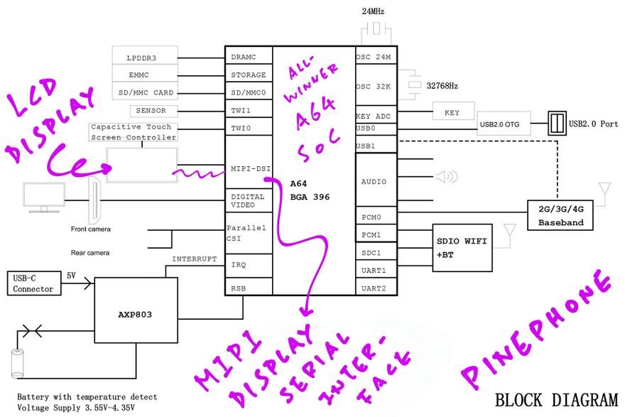
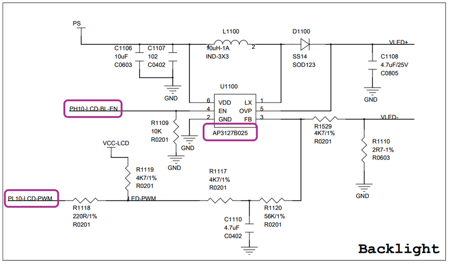
LCD Display on PinePhone Schematic (Page 2)
NuttX Driver for MIPI Display Serial Interface
The very first NuttX Driver we've implemented is for MIPI Display Serial Interface (DSI).
Why is MIPI DSI needed in PinePhone?
PinePhone talks to its LCD Panel (Xingbangda XBD599) via the MIPI DSI Bus on Allwinner A64 SoC.
That's why we need a MIPI DSI Driver in the NuttX Kernel.
So our MIPI DSI Driver will render graphics on PinePhone's LCD Display?
It gets complicated...
-
At Startup: Our driver sends MIPI DSI Commands to initialise PinePhone's LCD Controller: Sitronix ST7703
(ST7703 is inside the Xingbangda XBD599 LCD Panel)
-
After Startup: Allwinner A64's Display Engine and Timing Controller (TCON0) pump pixels continuously to the LCD Panel over MIPI DSI.
(Bypassing our MIPI DSI Driver)
Thus our MIPI DSI Driver is called only at startup to initialise the LCD Controller (ST7703).
Sounds super complicated...
Yep but this rendering design is super efficient!
PinePhone doesn't need to handle Interrupts while rendering the display... Everything is done in Hardware! (Allwinner A64 SoC)
The pixel data is pumped from RAM Framebuffers via Direct Memory Access (DMA). Which is also done in Hardware.
Let's dive inside our MIPI DSI Driver...
Composing a MIPI DSI Short Packet
Send MIPI DSI Packet
How do we send MIPI DSI Commands to PinePhone's LCD Controller?
Let's take one MIPI DSI Command that initialises the ST7703 LCD Controller: test_a64_mipi_dsi.c
// Command #1 to init ST7703
const uint8_t cmd1[] = {
  0xB9,  // SETEXTC (Page 131): Enable USER Command
  0xF1,  // Enable User command
  0x12,  // (Continued)
  0x83   // (Continued)
};

// Send the command to ST7703 over MIPI DSI
write_dcs(cmd1, sizeof(cmd1));
(ST7703 needs 20 Initialisation Commands)
write_dcs sends our command to the MIPI DSI Bus in 3 DCS Formats...
DCS Short Write: For commands with 1 Byte
DCS Short Write with Parameter: For commands with 2 Bytes
DCS Long Write: For commands with 3 Bytes or more
(DCS means Display Command Set)
/// Write the DCS Command to MIPI DSI
static int write_dcs(const uint8_t *buf, size_t len) {
  // Do DCS Short Write or Long Write depending on command length.
  // A64_MIPI_DSI_VIRTUAL_CHANNEL is 0.
  switch (len) {
    // DCS Short Write (without parameter)
    case 1:
      a64_mipi_dsi_write(A64_MIPI_DSI_VIRTUAL_CHANNEL,
        MIPI_DSI_DCS_SHORT_WRITE,
        buf, len);
      break;

    // DCS Short Write (with parameter)
    case 2:
      a64_mipi_dsi_write(A64_MIPI_DSI_VIRTUAL_CHANNEL,
        MIPI_DSI_DCS_SHORT_WRITE_PARAM,
        buf, len);
      break;

    // DCS Long Write
    default:
      a64_mipi_dsi_write(A64_MIPI_DSI_VIRTUAL_CHANNEL,
        MIPI_DSI_DCS_LONG_WRITE,
        buf, len);
      break;
  };
(We talk to MIPI DSI Bus on Virtual Channel 0)
a64_mipi_dsi_write comes from our NuttX MIPI DSI Driver: a64_mipi_dsi.c
// Transmit the payload data to the MIPI DSI Bus as a MIPI DSI Short or
// Long Packet. This function is called to initialize the LCD Controller.
// Assumes that the MIPI DSI Block has been enabled on the SoC.
// Returns the number of bytes transmitted.
ssize_t a64_mipi_dsi_write(
  uint8_t channel,       // Virtual Channel (0)
  enum mipi_dsi_e cmd,   // DCS Command (Data Type)
  const uint8_t *txbuf,  // Payload data for the packet
  size_t txlen)  // Length of payload data (Max 65541 bytes)
{
  ...
  // Compose Short or Long Packet depending on DCS Command
  switch (cmd) {
    // For DCS Long Write:
    // Compose Long Packet
    case MIPI_DSI_DCS_LONG_WRITE:
      pktlen = mipi_dsi_long_packet(pkt, sizeof(pkt), channel, cmd, txbuf, txlen);
      break;

    // For DCS Short Write (with and without parameter):
    // Compose Short Packet
    case MIPI_DSI_DCS_SHORT_WRITE:
      pktlen = mipi_dsi_short_packet(pkt, sizeof(pkt), channel, cmd, txbuf, txlen);
      break;

    case MIPI_DSI_DCS_SHORT_WRITE_PARAM:
      pktlen = mipi_dsi_short_packet(pkt, sizeof(pkt), channel, cmd, txbuf, txlen);
      break;
  };
Our NuttX Driver calls...
-
mipi_dsi_short_packet: Compose a MIPI DSI Short Packet
-
mipi_dsi_long_packet: Compose a MIPI DSI Long Packet
Then our NuttX Driver writes the Short or Long Packet to the MIPI DSI Registers of Allwinner A64: a64_mipi_dsi.c
  // Write the packet to DSI Low Power Transmit Package Register
  // at DSI Offset 0x300 (A31 Page 856)
  // A64_DSI_ADDR is the A64 DSI Base Address: 0x01ca0000
  addr = A64_DSI_ADDR + 0x300;
  for (i = 0; i < pktlen; i += 4) {

    // Fetch the next 4 bytes, fill with 0 if not available
    const uint32_t b[4] = {
      pkt[i],
      (i + 1 < pktlen) ? pkt[i + 1] : 0,
      (i + 2 < pktlen) ? pkt[i + 2] : 0,
      (i + 3 < pktlen) ? pkt[i + 3] : 0
    };

    // Merge the next 4 bytes into a 32-bit value
    const uint32_t v = b[0] + (b[1] << 8) + (b[2] << 16) + (b[3] << 24);

    // Write the 32-bit value to DSI Low Power Transmit Package Register
    modreg32(v, 0xffffffff, addr);
    addr += 4;
  }

  // Omitted: Wait for DSI Transmission to complete
And that's how our MIPI DSI Packet gets transmitted to the ST7703 LCD Controller, over the MIPI DSI Bus!
We do this 20 times, to send 20 Initialisation Commands to the ST7703 LCD Controller...
But wait... We haven't enabled the MIPI DSI Hardware yet!
Enable MIPI DSI and D-PHY
At startup we call the MIPI DSI Driver to send Initialisation Commands to the LCD Controller...
What about other MIPI DSI Operations?
Before sending MIPI DSI Packets, our NuttX Driver needs to enable 2 chunks of hardware on Allwinner A64 SoC...
-
Enable Allwinner A64's MIPI Display Serial Interface (DSI)
So we can send MIPI DSI commands to the LCD Panel.
We implemented this in a64_mipi_dsi_enable as a long list of A64 DSI Register Writes...
// DSI Instruction Function Register (Undocumented) // Set DSI_INST_ID_LP11 to 0x1f // Set DSI_INST_ID_TBA to 0x1000 0001 // Set DSI_INST_ID_HSC to 0x2000 0010 // Set DSI_INST_ID_HSD to 0x2000 000f putreg32(0x1f, DSI_INST_FUNC_REG(DSI_INST_ID_LP11)); putreg32(0x10000001, DSI_INST_FUNC_REG(DSI_INST_ID_TBA)); putreg32(0x20000010, DSI_INST_FUNC_REG(DSI_INST_ID_HSC)); putreg32(0x2000000f, DSI_INST_FUNC_REG(DSI_INST_ID_HSD)); ... -
Enable Allwinner A64's MIPI Display Physical Layer (D-PHY)
Which is the communications layer inside MIPI DSI.
We implemented this in a64_mipi_dphy_enable as a list of (undocumented) A64 D-PHY Register Writes...
// Power on DPHY Tx (Undocumented)
putreg32(0x10000000, DPHY_TX_CTL_REG);
putreg32(0xa06000e,  DPHY_TX_TIME0_REG);
putreg32(0xa033207,  DPHY_TX_TIME1_REG);
putreg32(0x1e,       DPHY_TX_TIME2_REG);
putreg32(0x0,        DPHY_TX_TIME3_REG);
putreg32(0x303,      DPHY_TX_TIME4_REG);
...
And after sending the MIPI DSI Packets to initialise our LCD Controller, we need to...
-
Start Allwinner A64's MIPI DSI in HSC and HSD Mode
That's High Speed Clock Mode with High Speed Data Transmission. (Which are probably needed by the Timing Controller TCON0)
We implemented this in a64_mipi_dsi_start as a list of (undocumented) A64 MIPI Register Writes..
// DSI Instruction Function Register (Undocumented)
// Set DSI_INST_FUNC_LANE_CEN (Bit 4) to 0
modreg32(0x0, DSI_INST_FUNC_LANE_CEN,
  DSI_INST_FUNC_REG(DSI_INST_ID_LP11));

// DSI Instruction Jump Select Register (Undocumented)
// Set to 0x63f0 7006
putreg32(0x63f07006, DSI_INST_JUMP_SEL_REG);
...
How did we create all this code for our NuttX Driver?
Our NuttX Driver for MIPI DSI (and MIPI D-PHY) lives in the NuttX Kernel as...
mipi_dsi.c: Compose MIPI DSI Packets (Long, Short, Short with Parameter)
a64_mipi_dsi.c: MIPI Display Serial Interface (DSI) for Allwinner A64
a64_mipi_dphy.c: MIPI Display Physical Layer (D-PHY) for Allwinner A64
We created the above NuttX Source Files by converting our MIPI DSI Driver from Zig to C...
display.zig: Zig Driver for MIPI DSI
dphy.zig: Zig Driver for MIPI D-PHY
(Why Zig? We'll come back to this)
We created the Zig Drivers by Reverse-Engineering the logs that we captured from PinePhone's p-boot Bootloader...
Why Reverse Engineer? Because a lot of details are missing from the official docs for Allwinner A64...
Let's talk about the Zig-to-C Conversion...
Convert Zig to C
Our NuttX Driver MIPI Driver was converted from Zig to C...
Was it difficult to convert Zig to C?
Not at all!
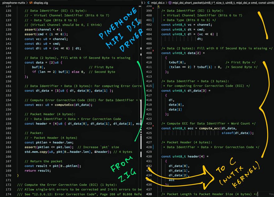
This is the Zig Code for our MIPI DSI Driver: display.zig
// Compose MIPI DSI Short Packet
fn composeShortPacket(
  pkt: []u8,    // Buffer for the returned packet
  channel: u8,  // Virtual Channel
  cmd: u8,      // DCS Command (Data Type)
  buf: [*c]const u8,  // Payload data for the packet
  len: usize          // Length of payload data (1 or 2 bytes)
) []const u8 {        // Returns the Short Packet
  // Data Identifier (DI) (1 byte):
  // - Virtual Channel Identifier (Bits 6 to 7)
  // - Data Type (Bits 0 to 5)
  const vc: u8 = channel;
  const dt: u8 = cmd;
  const di: u8 = (vc << 6) | dt;

  // Data (2 bytes), fill with 0 if Second Byte is missing
  const data = [2]u8 {
    buf[0],                       // First Byte
    if (len == 2) buf[1] else 0,  // Second Byte
  };

  // Data Identifier + Data (3 bytes): For computing Error Correction Code (ECC)
  const di_data = [3]u8 { di, data[0], data[1] };

  // Compute Error Correction Code (ECC) for Data Identifier + Word Count
  const ecc: u8 = computeEcc(di_data);

  // Packet Header (4 bytes):
  // - Data Identifier + Data + Error Correction Code
  const header = [4]u8 { di_data[0], di_data[1], di_data[2], ecc };

  // Packet:
  // - Packet Header (4 bytes)
  const pktlen = header.len;
  std.mem.copy(u8, pkt[0..header.len], &header); // 4 bytes

  // Return the packet
  const result = pkt[0..pktlen];
  return result;
}
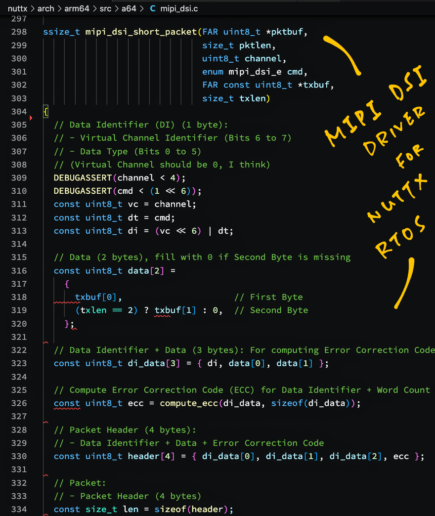
We manually converted the Zig code to C like so: mipi_dsi.c
// Compose MIPI DSI Short Packet.
// Returns the Packet Length.
ssize_t mipi_dsi_short_packet(
  uint8_t *pktbuf,       // Buffer for the returned packet
  size_t pktlen,         // Size of the packet buffer
  uint8_t channel,       // Virtual Channel
  enum mipi_dsi_e cmd,   // DCS Command (Data Type)
  const uint8_t *txbuf,  // Payload data for the packet
  size_t txlen)          // Length of payload data (1 or 2 bytes)
{
  // Data Identifier (DI) (1 byte):
  // Virtual Channel Identifier (Bits 6 to 7)
  // Data Type (Bits 0 to 5)
  const uint8_t vc = channel;
  const uint8_t dt = cmd;
  const uint8_t di = (vc << 6) | dt;

  // Data (2 bytes): Fill with 0 if Second Byte is missing
  const uint8_t data[2] = {
    txbuf[0],                     // First Byte
    (txlen == 2) ? txbuf[1] : 0,  // Second Byte
  };

  // Data Identifier + Data (3 bytes):
  // For computing Error Correction Code (ECC)
  const uint8_t di_data[3] = { di, data[0], data[1] };

  // Compute ECC for Data Identifier + Word Count
  const uint8_t ecc = compute_ecc(di_data, sizeof(di_data));

  // Packet Header (4 bytes):
  // Data Identifier + Data + Error Correction Code
  const uint8_t header[4] = { di_data[0], di_data[1], di_data[2], ecc };

  // Packet Length is Packet Header Size (4 bytes)
  const size_t len = sizeof(header);

  // Copy Packet Header to Packet Buffer
  memcpy(pktbuf, header, sizeof(header));  // 4 bytes

  // Return the Packet Length
  return len;
}
The C Code looks highly similar to the original Zig Code! Thus manually converting Zig to C (line by line) is a piece of cake.
(According to Matheus Catarino França, the Zig-to-C Auto-Translation might work too)
Test MIPI DSI Driver
Our NuttX Display Driver for PinePhone is incomplete...
How do we test the MIPI DSI Driver in the NuttX Kernel?
Right now we have implemented the following in the NuttX Kernel...
-
Driver for MIPI Display Serial Interface (DSI)
-
Driver for MIPI Display Physical Layer (D-PHY)
But to render graphics on PinePhone we need the following drivers, which are still in Zig (pending conversion to C)...
- Driver for Display Backlight
- Driver for Timing Controller TCON0
- Driver for Power Management Integrated Circuit
- Driver for LCD Panel
- Driver for Display Engine
Running an Integration Test across the C and Zig Drivers will be a little tricky. This is how we run the test...
We created this program in Zig that calls the C and Zig Drivers, in the right sequence: render.zig
/// Main Function that will be called by NuttX
/// when we run the `hello` app
pub export fn hello_main(argc: c_int, argv: [*c]const [*c]u8) c_int {
  // Render graphics on PinePhone in Zig and C...
  // Turn on Display Backlight (in Zig)
  // Init Timing Controller TCON0 (in Zig)
  // Init PMIC (in Zig)

  backlight.backlight_enable(90);
  tcon.tcon0_init();
  pmic.display_board_init();

  // Enable MIPI DSI Block (in C)
  // Enable MIPI Display Physical Layer (in C)

  _ = a64_mipi_dsi_enable();
  _ = a64_mipi_dphy_enable();

  // Reset LCD Panel (in Zig)
  panel.panel_reset();

  // Init LCD Panel (in C)
  // Start MIPI DSI HSC and HSD (in C)

  _ = pinephone_panel_init();
  _ = a64_mipi_dsi_start();

  // Init Display Engine (in Zig)
  // Wait a while
  // Render Graphics with Display Engine (in Zig)

  de2_init();
  _ = c.usleep(160000);
  renderGraphics(3);  // Render 3 UI Channels
(pinephone_panel_init is defined here)
Then we compile our Zig Test Program (targeting PinePhone) and link it with NuttX...
##  Configure NuttX
cd nuttx
./tools/configure.sh pinephone:nsh
make menuconfig

##  Select "System Type > Allwinner A64 Peripheral Selection > MIPI DSI"
##  Select "Build Setup > Debug Options > Graphics Debug Features > Graphics Errors / Warnings / Informational Output"
##  Save and exit menuconfig

##  Build NuttX
make

##  Download the Zig Test Program
pushd $HOME
git clone https://github.com/lupyuen/pinephone-nuttx
cd pinephone-nuttx

##  Compile the Zig App for PinePhone
##  (armv8-a with cortex-a53)
##  TODO: Change "$HOME/nuttx" to your NuttX Project Directory
zig build-obj \
  --verbose-cimport \
  -target aarch64-freestanding-none \
  -mcpu cortex_a53 \
  -isystem "$HOME/nuttx/nuttx/include" \
  -I "$HOME/nuttx/apps/include" \
  render.zig

##  Copy the compiled app to NuttX and overwrite `hello.o`
##  TODO: Change "$HOME/nuttx" to your NuttX Project Directory
cp render.o \
  $HOME/nuttx/apps/examples/hello/*hello.o

##  Return to the NuttX Folder
popd

##  Link the Compiled Zig App with NuttX
make
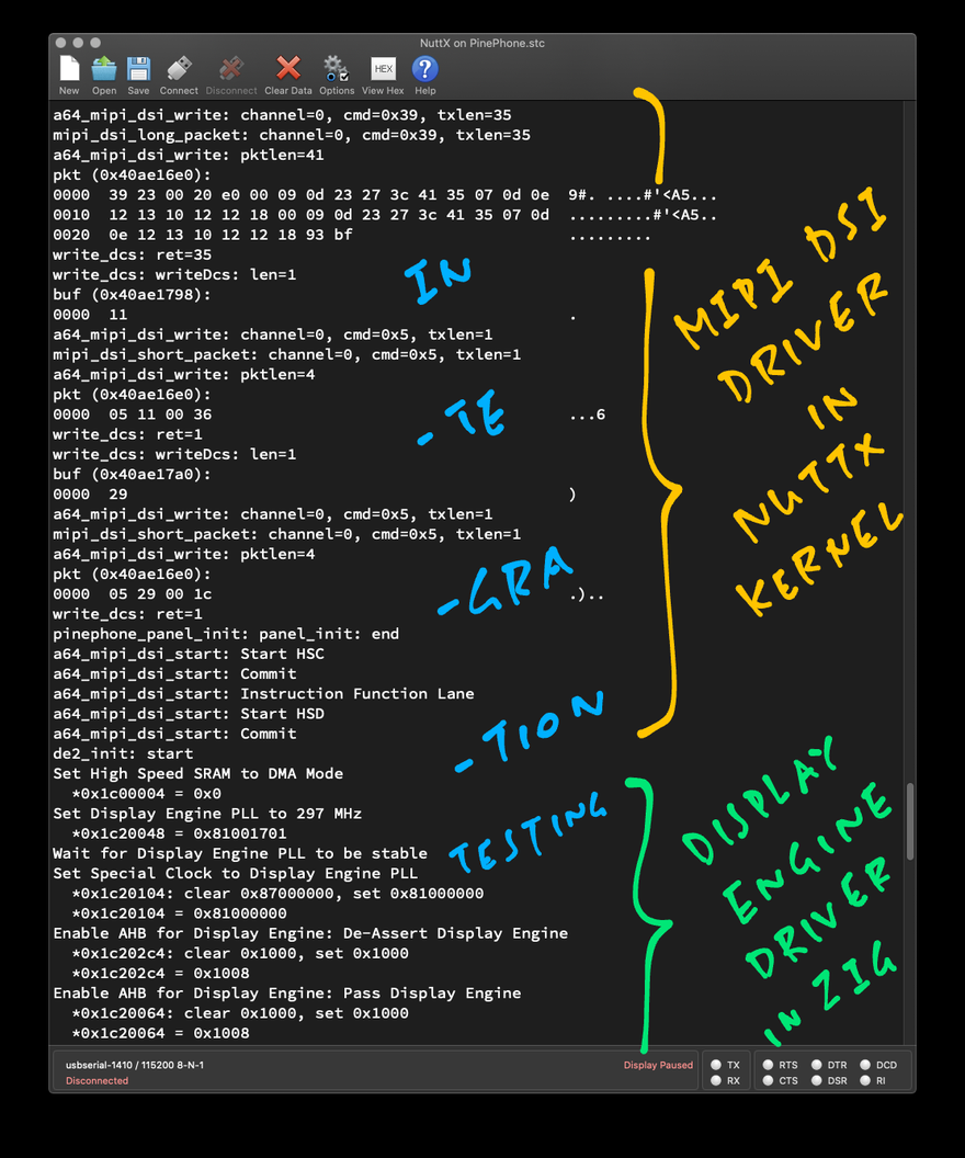
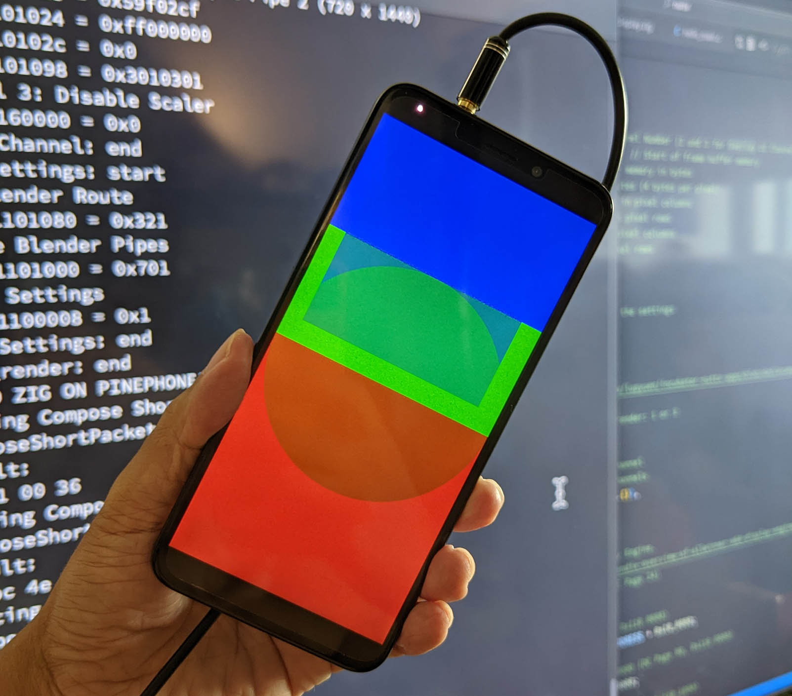
We boot NuttX on PinePhone (via microSD) and run the Zig Test Program (pic above)...
NuttShell (NSH) NuttX-11.0.0-pinephone

nsh> uname -a
NuttX 11.0.0-pinephone 2a1577a-dirty Dec  9 2022 13:57:47 arm64 pinephone

nsh> hello 0
Yep our Zig Test Program renders the Test Pattern successfully on PinePhone's LCD Display! (Like this)
Which means the NuttX Kernel Driver for MIPI DSI is working OK!
Here's the Test Log for our Zig Test Program running on NuttX and PinePhone...
Unit Testing
What about Unit Testing? Can we test the MIPI DSI Driver without Zig?
Yep! Our MIPI DSI Driver simply writes values to a bunch of A64 Hardware Registers, like so: a64_mipi_dsi.c
// DSI Configuration Register 1 (A31 Page 846)
// Set Video_Start_Delay (Bits 4 to 16) to 1468 (Line Delay)
// Set Video_Precision_Mode_Align (Bit 2) to 1 (Fill Mode)
// Set Video_Frame_Start (Bit 1) to 1 (Precision Mode)
// Set DSI_Mode (Bit 0) to 1 (Video Mode)
#define DSI_BASIC_CTL1_REG (A64_DSI_ADDR + 0x14)
#define DSI_MODE                   (1 << 0)
#define VIDEO_FRAME_START          (1 << 1)
#define VIDEO_PRECISION_MODE_ALIGN (1 << 2)
#define VIDEO_START_DELAY(n)       ((n) << 4)

dsi_basic_ctl1 = VIDEO_START_DELAY(1468) |
                  VIDEO_PRECISION_MODE_ALIGN |
                  VIDEO_FRAME_START |
                  DSI_MODE;
putreg32(dsi_basic_ctl1, DSI_BASIC_CTL1_REG);

// Include Test Code to verify Register Addresses and Written Values
#include "../../pinephone-nuttx/test/test_a64_mipi_dsi2.c"
So we only need to ensure that the Hardware Register Addresses and the Written Values are correct.
To do that, we use Assertion Checks to verify the Addresses and Values: test_a64_mipi_dsi2.c
// Test Code to verify Register Addresses and Written Values
DEBUGASSERT(DSI_BASIC_CTL1_REG == 0x1ca0014);
DEBUGASSERT(dsi_basic_ctl1 == 0x5bc7);
If the Addresses or Values are incorrect, our MIPI DSI Driver halts with an Assertion Failure.
(We remove the Assertion Checks in the final version of our driver)
What about a smaller, self-contained Unit Test for MIPI DSI?
This is the Unit Test that verifies our NuttX Driver correctly composes MIPI DSI Packets (Long / Short / Short with Parameter)...
- mipi_dsi_test: Unit Test for MIPI DSI Packets
We run this Unit Test locally on our computer, here's how...
Local Testing
Can we test the MIPI DSI Driver on our Local Computer? Without running on PinePhone?
Most certainly! In fact we test the MIPI DSI Driver on our Local Computer first before testing on PinePhone. Here's how...
Remember that our MIPI DSI Driver simply writes values to a bunch of A64 Hardware Registers. So we only need to ensure that the Hardware Register Addresses and the Written Values are correct.
To target our Local Computer, we created a Test Scaffold that simulates the NuttX Build Environment: test.c
// Simulate NuttX Build Environment
#include <nuttx/arch.h>
#include "arm64_arch.h"
#include "mipi_dsi.h"
#include "a64_mipi_dsi.h"
#include "a64_mipi_dphy.h"

// Test Scaffold for Local Testing
int main() {

  // Test: Enable MIPI DSI Block
  a64_mipi_dsi_enable();

  // Test: Enable MIPI Display Physical Layer (DPHY)
  a64_mipi_dphy_enable();

  // Test: Initialise LCD Controller (ST7703)
  pinephone_panel_init();

  // Test: Start MIPI DSI HSC and HSD
  a64_mipi_dsi_start();

  // Test: MIPI DSI Packets
  mipi_dsi_test();
}
Then we compile the Test Scaffold and run it on our Local Computer: run.sh
## Compile Test Code for Local Testing
gcc \
  -o test \
  -I . \
  -I ../../nuttx/arch/arm64/src/a64 \
  test.c \
  ../../nuttx/arch/arm64/src/a64/a64_mipi_dphy.c \
  ../../nuttx/arch/arm64/src/a64/a64_mipi_dsi.c \
  ../../nuttx/arch/arm64/src/a64/mipi_dsi.c

## Run the Local Test
./test

## Capture the Actual Test Log
./test >test.log

## Diff the Actual and Expected Test Logs
diff \
  --ignore-all-space \
  expected.log \
  test.log
Note that we capture the Actual Test Log and we diff it with the Expected Test Log.
That's how we detect discrepancies in the Register Addresses and the Written Values...
Enable MIPI DSI Bus
  *0x1c20060: clear 0x2, set 0x2
  *0x1c202c0: clear 0x2, set 0x2
Enable DSI Block
  *0x1ca0000 = 0x1
  *0x1ca0010 = 0x30000
  *0x1ca0060 = 0xa
  *0x1ca0078 = 0x0
Set Instructions
  *0x1ca0020 = 0x1f
  *0x1ca0024 = 0x10000001
  *0x1ca0028 = 0x20000010
  *0x1ca002c = 0x2000000f
  *0x1ca0030 = 0x30100001
  *0x1ca0034 = 0x40000010
  *0x1ca0038 = 0xf
  *0x1ca003c = 0x5000001f
  ...
Let's talk about the missing parts of our NuttX Driver...
Inside our Complete Display Driver for PinePhone
Upcoming NuttX Drivers
What about the rest of our NuttX Display Driver?
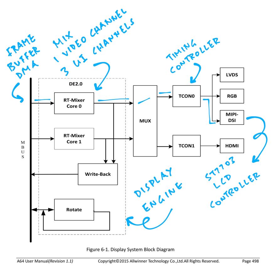
We talked earlier about the Grand Plan for our NuttX Display Driver (pic above) that's deeply layered like an Onion Kueh Lapis...
Today we've implemented the MIPI Display Serial Interface and MIPI Display Physical Layer for our NuttX Display Driver (lower part of pic above)...
-
Enable Allwinner A64's MIPI Display Serial Interface (DSI)
(So we can send MIPI DSI commands to the LCD Panel)
-
Enable Allwinner A64's MIPI Display Physical Layer (D-PHY)
(Which is the communications layer inside MIPI DSI)
-
Initialise PinePhone's LCD Controller (Sitronix ST7703)
(Send the Initialisation Commands over MIPI DSI)
-
Start Allwinner A64's MIPI DSI in HSC and HSD Mode
(High Speed Clock Mode with High Speed Data Transmission)
We're now building the NuttX Drivers for the remaining features (upper part of pic above), converting our Zig code to C...
-
Timing Controller (TCON0): To render PinePhone's LCD Display, the MIPI DSI Controller on Allwinner A64 needs to receive a continuous stream of pixels...
Which will be provided by Allwinner A64's Timing Controller (TCON0).
(TCON0 will receive the pixel stream from A64's Display Engine)
Our NuttX Driver shall program TCON0 to send the stream of pixels to the MIPI DSI Controller.
This will be implemented in our new Timing Controller (TCON0) Driver for NuttX.
-
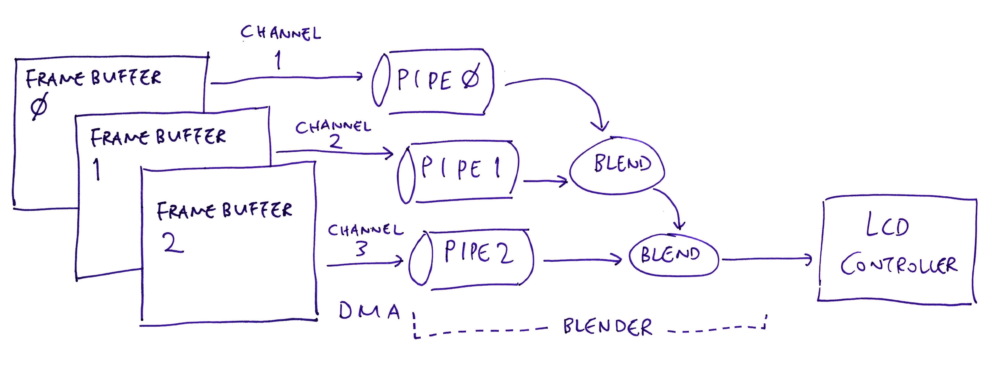
Display Engine (DE): Allwinner A64's Display Engine (DE) reads the Graphics Framebuffers in RAM (up to 3 Framebuffers)...
And streams the pixels to the Timing Controller (TCON0).
Our NuttX Driver shall configure DE to read the Framebuffers via Direct Memory Access (DMA).
With DMA, updates to the Framebuffers will be instantly visible on PinePhone's LCD Display.
This will be implemented in our new Display Engine Driver for NuttX.
-
Display Backlight: We won't see anything on PinePhone's LCD Display... Until we switch on the Display Backlight!
PinePhone's Display Backlight is controlled by A64's...
Programmable Input / Output (PIO): Works like GPIO, implemented in a64_pio.c
Pulse-Width Modulation (PWM): To be implemented
To turn on the Display Backlight, we'll call PIO and PWM in our new Board LCD Driver for NuttX.
-
LCD Panel: Before sending Initialisation Commands to the ST7703 LCD Controller, we need to reset the LCD Panel.
We do this with Allwinner A64's Programmable Input / Output (PIO), implemented in a64_pio.c. (Works like GPIO)
To reset the LCD Panel, we'll call PIO in our new Board LCD Driver for NuttX.
-
Power Management Integrated Circuit (PMIC): To power on the LCD Display, we need to program PinePhone's Power Management Integrated Circuit (PMIC).
The AXP803 PMIC is connected on Allwinner A64's Reduced Serial Bus (RSB). (Works like I2C)
We'll control the PMIC over RSB in our new Board LCD Driver for NuttX.
Very soon the official NuttX Kernel will be rendering graphics on PinePhone's LCD Display. Stay Tuned!
Why Zig
Why did we start with Zig? Why not code directly in C?
Building a NuttX Display Driver for PinePhone feels like a risky challenge...
Allwinner A64's Display Interfaces are poorly documented
11 Steps to be executed precisely, in the right sequence
We need an efficient way to Experiment, Backtrack and Redo things in our driver
Zig seems to work really well because...
Our complete Display Driver Protoype was created in 9 Weeks
Zig's Safety Checks were super helpful for catching bugs
Converting Zig to C was easy
Along the way we created an Executable Specification of Allwinner A64's Display Interfaces... A huge bunch of Hardware Register Addresses and their Expected Values: display.zig
// Set Video Start Delay
// DSI_BASIC_CTL1_REG: DSI Offset 0x14 (A31 Page 846)
// Set Video_Start_Delay (Bits 4 to 16) to 1468 (Line Delay)
// Set Video_Precision_Mode_Align (Bit 2) to 1 (Fill Mode)
// Set Video_Frame_Start (Bit 1) to 1 (Precision Mode)
// Set DSI_Mode (Bit 0) to 1 (Video Mode)
// Note: Video_Start_Delay is actually 13 bits, not 8 bits as documented in the A31 User Manual

const DSI_BASIC_CTL1_REG = DSI_BASE_ADDRESS + 0x14;
comptime{ assert(DSI_BASIC_CTL1_REG == 0x1ca0014); }

const Video_Start_Delay:          u17 = 1468 << 4;
const Video_Precision_Mode_Align: u3  = 1    << 2;
const Video_Frame_Start:          u2  = 1    << 1;
const DSI_Mode:                   u1  = 1    << 0;
const DSI_BASIC_CTL1 = Video_Start_Delay
  | Video_Precision_Mode_Align
  | Video_Frame_Start
  | DSI_Mode;
comptime{ assert(DSI_BASIC_CTL1 == 0x5bc7); }
putreg32(DSI_BASIC_CTL1, DSI_BASIC_CTL1_REG);  // TODO: DMB
Which is really neat because...
Our Executable Spec describes Allwinner A64's Display Interfaces in a concise and readable format
"
comptimeassert" will verify our Register Adresses and Values at Compile-TimeLess Ambiguity: Zig Integers won't overflow, Zig Arrays are bounded
Can be translated into C or Rust for other Operating Systems
With the Executable Spec, maybe someday we'll emulate PinePhone Hardware with QEMU or FPGA!
Was it worth the effort? Would you do it again in Zig?
Yes and yes! Zig is excellent for prototyping new Device Drivers for Operating Systems.
Once again... Why are we doing all this?
PinePhone is becoming popular as the Edgy, Alternative Smartphone for folks who love to tinker with their gadgets. (And it's still in stock!)
The best way to understand what's really inside PinePhone: Creating our own PinePhone Display Driver.
That's why we're doing all this PinePhone Reverse-Engineering... First to Zig, then to C!
What about other cool open-source Allwinner A64 gadgets like TERES-I?
Someday we might! But first let's uncover all the secrets inside PinePhone.

Testing our PinePhone Display Driver on Apache NuttX RTOS
What's Next
Very soon the official NuttX Kernel will be rendering graphics on PinePhone's LCD Display!
-
We've seen the 11 Steps needed to create a Complete Display Driver for PinePhone
(MIPI DSI, Timing Controller, Display Engine, PMIC, ...)
-
We've implemented the NuttX Kernel Driver for MIPI Display Serial Interface
(Which completes 4 of the 11 Steps)
-
We're now building the missing pieces of our PinePhone Display Driver
(Including the super-complicated Display Engine Driver)
-
We chose the Zig Programming Language for Reverse-Engineering the PinePhone Display Driver, before converting to C
(And it's working rather well)
Stay Tuned for Updates!
Check out the other articles on NuttX RTOS for PinePhone...
Many Thanks to my GitHub Sponsors for supporting my work! This article wouldn't have been possible without your support.
Got a question, comment or suggestion? Create an Issue or submit a Pull Request here...
Inside our Complete Display Driver for PinePhone
Appendix: Upcoming NuttX Drivers
We talked earlier about our implementation of the MIPI Display Serial Interface and MIPI Display Physical Layer for our NuttX Display Driver (lower part of pic above)...
This section explains how we're building the NuttX Drivers for the remaining features (upper part of pic above), by converting our Zig Drivers to C...
Allwinner A64 Timing Controller (TCON0)
Timing Controller (TCON0)
To render PinePhone's LCD Display, the MIPI DSI Controller on Allwinner A64 needs to receive a continuous stream of pixels...
Which will be provided by Allwinner A64's Timing Controller (TCON0).
(TCON0 will receive the pixel stream from A64's Display Engine)
Our NuttX Driver shall program TCON0 to send the stream of pixels to the MIPI DSI Controller.
This will be implemented in our new Timing Controller (TCON0) Driver for NuttX...
We'll convert the above TCON0 Driver from Zig to C.
Display Engine
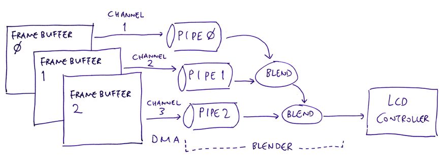
Allwinner A64's Display Engine (DE) reads the Graphics Framebuffers in RAM (up to 3 Framebuffers, pic above)...
And streams the pixels to the ST7703 LCD Controller for display, via the A64 Timing Controller (TCON0).
Our NuttX Driver shall configure DE to read the Framebuffers via Direct Memory Access (DMA). With DMA, updates to the Framebuffers will be instantly visible on PinePhone's LCD Display.
This will be implemented in our new Display Engine Driver for NuttX in two parts...
-
Initialise the A64 Display Engine to send the pixel stream to TCON0
-
Configure the A64 Display Engine to read Framebuffers over DMA
We'll convert the above Zig Drivers to C.
Our Display Engine Driver shall follow the design of the STM32F7 Display Driver in NuttX...
-
At startup, stm32_bringup calls fb_register
-
To initialise the Framebuffer, fb_register calls up_fbinitialize
-
To initialise the Display Driver, up_fbinitialize calls stm32_ltdcinitialize
-
Inside the Display Driver, stm32_ltdcinitialize creates the NuttX Framebuffer
NuttX Framebuffer is here: stm32_ltdc.c
Display Backlight
We won't see anything on PinePhone's LCD Display... Until we switch on the Display Backlight!
PinePhone's Display Backlight is controlled by A64's...
Programmable Input / Output (PIO): Works like GPIO, implemented in a64_pio.c
Pulse-Width Modulation (PWM): To be implemented
To turn on the Display Backlight, we'll call PIO and PWM in our new Board LCD Driver for NuttX...
We'll convert the above Backlight Driver from Zig to C.
Our Backlight Driver will follow the design of the STM32 Backlight Driver: stm32_backlight...
The driver code will go inside our new Board LCD Driver for NuttX, similar to this...
LCD Panel
Before sending Initialisation Commands to the ST7703 LCD Controller, we need to reset the LCD Panel.
We do this with Allwinner A64's Programmable Input / Output (PIO), implemented in a64_pio.c. (Works like GPIO)
To reset the LCD Panel, we'll call PIO in our new Board LCD Driver for NuttX...
We'll convert the above LCD Panel Driver from Zig to C.
The code will go inside our new Board LCD Driver for NuttX, similar to this...
Also in the Board LCD Driver: We'll add the code to send the Initialisation Commands to the ST7703 LCD Controller (via MIPI DSI)...
We have already converted the Zig code to C.
Power Management Integrated Circuit
To power on the LCD Display, we need to program PinePhone's Power Management Integrated Circuit (PMIC).
The AXP803 PMIC is connected on Allwinner A64's Reduced Serial Bus (RSB). (Works like I2C)
We'll control the PMIC over RSB in our new Board LCD Driver for NuttX...
We'll convert the above PMIC Driver from Zig to C.
The code will go inside our new Board LCD Driver for NuttX, similar to this...


Top comments (2)
Wow! Fantastic article! I love Pine64 and love Zig, I'll keep an eye on NuttX, seems cool
Thank you so much! :-)