What happens when we render graphics on PinePhone's LCD Display?
Plenty happens when we render graphics on Pine64 PinePhone (pic above)... Because PinePhone's Display Hardware is so complex!
To understand the internals of PinePhone, let's build a Display Driver that will talk directly to PinePhone's Display Hardware. ("Bare Metal")
We'll do this with the Zig Programming Language, running on Apache NuttX RTOS.
Why Zig? Why not C?
We could have done it in C... But our driver code in Zig looks neater, more concise and (hopefully) easier to understand.
So instead of writing this in C...
// In C: Get the framebuffer length
int len = sizeof(framebuffer)
  / sizeof(framebuffer[0]);
We use the shorter readable form in Zig...
// In Zig: Get the framebuffer length
const len = framebuffer.len;
Zig looks highly similar to C. If we ever need to convert the driver code to C... Easy peasy!
(In this article we'll explain the tricky Zig parts with C)
Why NuttX on PinePhone?
Apache NuttX RTOS gives us direct access to PinePhone's Hardware Registers, so nothing gets in our way. (Like Memory Protection)
(NuttX boots from microSD, so it won't affect the Linux Distro installed on PinePhone)
The code that we discuss today will soon become the PinePhone Display Driver for NuttX RTOS.
Let's continue the journey from our NuttX Porting Journal...
Graphics Framebuffer
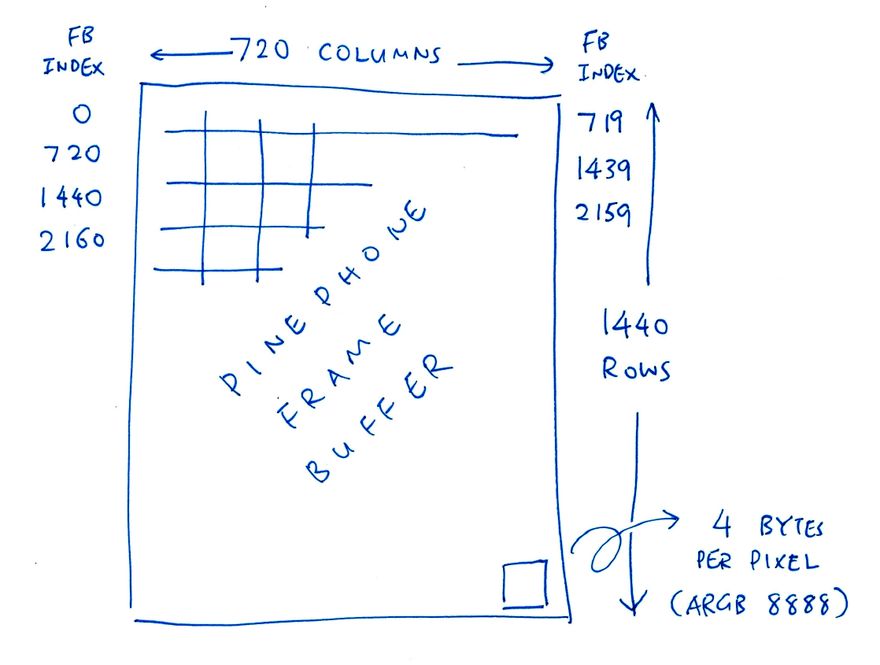
We begin with a Graphics Framebuffer that we'll render on PinePhone's 720 x 1440 display (pic above): render.zig
// Framebuffer of 720 x 1440 pixels
var fb0 = std.mem.zeroes(  // Init to zeroes...
  [720 * 1440] u32         // 720 x 1440 pixels
);                         // (4 bytes per pixel: XRGB 8888)
Each pixel is u32, equivalent to uint32_t in C.
std.mem.zeroes allocates an array of 720 x 1440 pixels, filled with zeroes.
Each pixel has the format ARGB 8888 (32 bits)...
Alpha: 8 bits
Red: 8 bits
Green: 8 bits
Blue: 8 bits
So 0x8080 0000 is Semi-Transparent Red. (Alpha: 0x80, Red: 0x80)
Let's describe the Framebuffer with a NuttX Struct: render.zig
/// NuttX Color Plane for PinePhone (Base UI Channel):
/// Fullscreen 720 x 1440 (4 bytes per XRGB 8888 pixel)
const planeInfo = c.fb_planeinfo_s {
  .fbmem   = &fb0,     // Start of frame buffer memory
  .fblen   = @sizeOf( @TypeOf(fb0) ),  // Length of frame buffer memory in bytes
  .stride  = 720 * 4,  // Length of a line in bytes (4 bytes per pixel)
  .display = 0,        // Display number (Unused)
  .bpp     = 32,       // Bits per pixel (XRGB 8888)
  .xres_virtual = 720,   // Virtual Horizontal resolution in pixel columns
  .yres_virtual = 1440,  // Virtual Vertical resolution in pixel rows
  .xoffset      = 0,     // Offset from virtual to visible resolution
  .yoffset      = 0,     // Offset from virtual to visible resolution
};
(fb_planeinfo_s comes from NuttX RTOS)
Later we'll pass the above values to render the Framebuffer: render.zig
// Init the Base UI Channel with the Framebuffer
initUiChannel(
  1,  // UI Channel Number (1 for Base UI Channel)
  planeInfo.fbmem,    // Start of frame buffer memory
  planeInfo.fblen,    // Length of frame buffer memory in bytes
  planeInfo.stride,   // Length of a line in bytes (4 bytes per pixel)
  planeInfo.xres_virtual,  // Horizontal resolution in pixel columns
  planeInfo.yres_virtual,  // Vertical resolution in pixel rows
  planeInfo.xoffset,  // Horizontal offset in pixel columns
  planeInfo.yoffset,  // Vertical offset in pixel rows
);
But first we paint some colours...
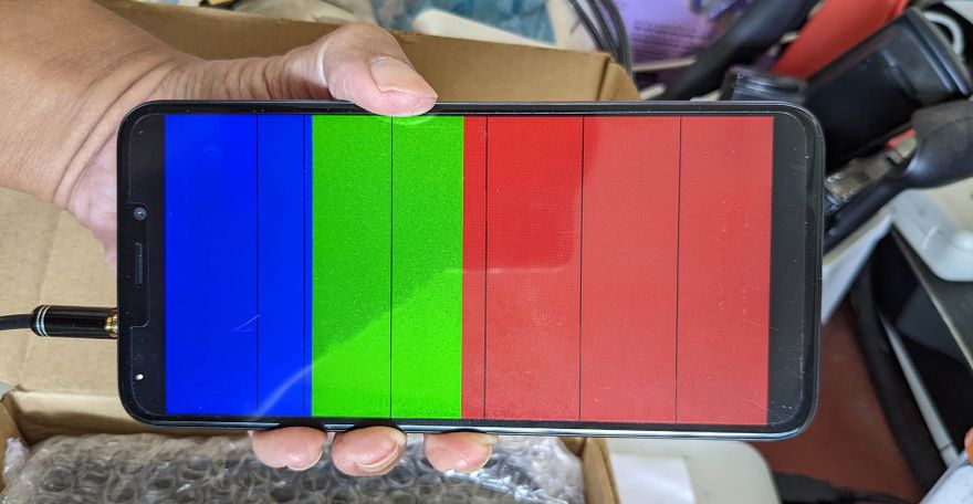
Fill Framebuffer
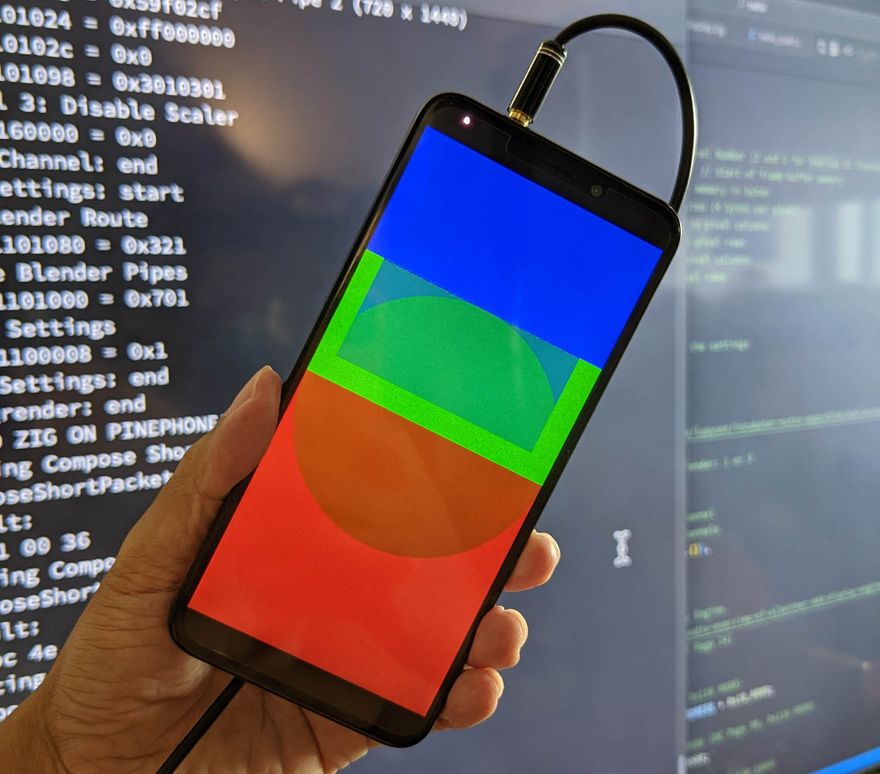
This is how we fill the Framebuffer with Blue, Green and Red (pic above): render.zig
// Fill Framebuffer with Blue, Green and Red
var i: usize = 0;  // usize is similar to size_t
while (i < fb0.len) : (i += 1) {

  // Colours are in XRGB 8888 format
  if (i < fb0.len / 4) {
    // Blue for top quarter
    fb0[i] = 0x8000_0080;
  } else if (i < fb0.len / 2) {
    // Green for next quarter
    fb0[i] = 0x8000_8000;
  } else {
    // Red for lower half
    fb0[i] = 0x8080_0000;
  }
}
(Yeah Zig's while loop looks rather odd, but there's a simpler way to iterate over arrays: for loop)
Remember that pixels are in 32-bit ARGB 8888 format. So 0x8080 0000 means...
Alpha (8 bits):
0x80Red (8 bits):
0x80Green (8 bits):
0x00Blue (8 bits):
0x00
(Or Semi-Transparent Red)
We're now ready to render our Framebuffer!
Does PinePhone support multiple Framebuffers?
Yep PinePhone supports 3 Framebuffers: One Base Framebuffer plus 2 Overlay Framebuffers: render.zig
/// NuttX Video Controller for PinePhone (3 UI Channels)
const videoInfo = c.fb_videoinfo_s {
  .fmt       = c.FB_FMT_RGBA32,  // Pixel format (XRGB 8888)
  .xres      = 720,   // Horizontal resolution in pixel columns
  .yres      = 1440,  // Vertical resolution in pixel rows
  .nplanes   = 1,     // Number of color planes supported (Base UI Channel)
  .noverlays = 2,     // Number of overlays supported (2 Overlay UI Channels)
};
(fb_videoinfo_s comes from NuttX RTOS)
We'll test the Overlay Framebuffers later.
Configure Framebuffer
How do we render the Framebuffer on PinePhone?
Remember that we're talking directly to PinePhone's Display Hardware ("Bare Metal"), without any Display Driver. So this part might sound a little more complicated than we expect...
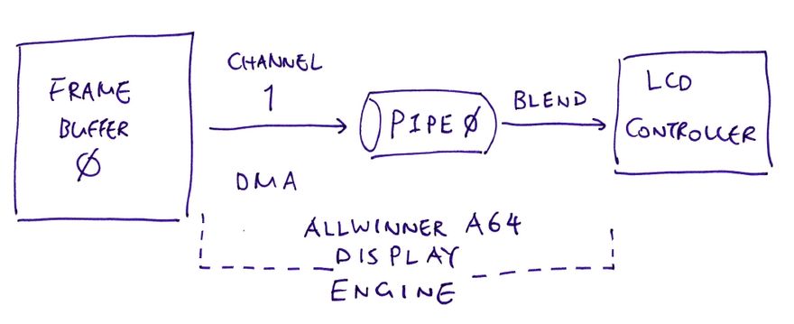
To control PinePhone's Display Hardware, we'll set the Hardware Registers for the Allwinner A64 Display Engine inside PinePhone. (Pic above)
In a while we'll do the following through the Hardware Registers...
-
Set Framebuffer Address
(To activate DMA: Direct Memory Access)
-
Set Framebuffer Pitch
(Number of bytes per row: 720 * 4)
-
Set Framebuffer Size
(Width and Height are 720 x 1440)
-
Set Framebuffer Coordinates
(X and Y Offsets are 0)
-
Set Framebuffer Attributes
(Global Alpha Values)
-
Disable Framebuffer Scaler
(Because we're not scaling the graphics)
This sounds really low level... But hopefully we'll learn more about PinePhone's Internals!
How do we get the above Framebuffer values?
Our program calls initUiChannel, passing the Framebuffer Settings: render.zig
// Init the Base UI Channel with the Framebuffer
initUiChannel(
  1,  // UI Channel Number (1 for Base UI Channel)
  planeInfo.fbmem,    // Start of frame buffer memory
  planeInfo.fblen,    // Length of frame buffer memory in bytes
  planeInfo.stride,   // Length of a line in bytes (4 bytes per pixel)
  planeInfo.xres_virtual,  // Horizontal resolution in pixel columns
  planeInfo.yres_virtual,  // Vertical resolution in pixel rows
  planeInfo.xoffset,  // Horizontal offset in pixel columns
  planeInfo.yoffset,  // Vertical offset in pixel rows
);
(We've seen planeInfo earlier)
Our function initUiChannel is defined in render.zig
/// Initialise a UI Channel for PinePhone's A64 Display Engine.
/// We use 3 UI Channels: Base UI Channel (#1) plus 2 Overlay UI Channels (#2, #3).
/// See https://lupyuen.github.io/articles/de#appendix-programming-the-allwinner-a64-display-engine
fn initUiChannel(
  comptime channel: u8,   // UI Channel Number: 1, 2 or 3
  fbmem: ?*anyopaque,     // Start of frame buffer memory, or null if this channel should be disabled
  comptime fblen: usize,           // Length of frame buffer memory in bytes
  comptime stride:  c.fb_coord_t,  // Length of a line in bytes (4 bytes per pixel)
  comptime xres:    c.fb_coord_t,  // Horizontal resolution in pixel columns
  comptime yres:    c.fb_coord_t,  // Vertical resolution in pixel rows
  comptime xoffset: c.fb_coord_t,  // Horizontal offset in pixel columns
  comptime yoffset: c.fb_coord_t,  // Vertical offset in pixel rows
) void {
  ...
Which means that our function initUiChannel will receive the following values...
-
channelis1(We'll see Channels 2 and 3 later)
-
fbmemisfb0(Framebuffer Address)
-
fblenis720 * 1280 * 4(Framebuffer Size in Bytes)
-
strideis720 * 4(Number of Bytes in a Row)
-
xresis720(Framebuffer Width)
-
yresis1440(Framebuffer Height)
-
xoffsetis0(Framebuffer X Offset)
-
yoffsetis0(Framebuffer Y Offset)
Why is the Framebuffer Address declared as "?*anyopaque"?
That's because...
"
*anyopaque" is similar to "void *" in C (non-null)"
?*anyopaque" is the same, except that null values are allowed
So the Framebuffer Address can be null.
(Which will disable the Overlay Framebuffers)
What's comptime?
comptime substitutes the Parameter Values at Compile-Time. (Somewhat like a C Macro)
We'll explain why in a while.
Let's look inside our function initUiChannel...
Framebuffer Address
The first Hardware Register we'll set is the Framebuffer Address: render.zig
// OVL_UI_TOP_LADD (UI Overlay Top Field Memory Block Low Address)
// At OVL_UI Offset 0x10
// Set to Framebuffer Address fb0
// (DE Page 104)

const ptr = @ptrToInt(fbmem.?);
const OVL_UI_TOP_LADD =
  OVL_UI_BASE_ADDRESS + 0x10;
putreg32(              // Write to Hardware Register...
  @intCast(u32, ptr),  // Value
  OVL_UI_TOP_LADD      // Address
);
(Recall that fbmem is the Address of fb0)
For our safety, Zig gets strict about Null Values and Range Checking...
-
fbmem.?returns the non-null value offbmem(It halts with a Runtime Panic if null)
@ptrToIntconvertsfbmemfrom 64-bit Pointer to 64-bit Integer-
@intCastconverts the 64-bit Integer to 32-bit(It halts if it won't fit)
-
putreg32writes the 32-bit Integer to the Address of the Hardware Register
Huh we're force-fitting a 64-bit Physical Address into a 32-bit Integer?
That's perfectly OK because PinePhone only supports up to 3 GB of Physical RAM.
What's OVL_UI_BASE_ADDRESS?
OVL_UI_BASE_ADDRESS is computed though a chain of Hardware Register addresses: render.zig
// OVL_UI(CH1) (UI Overlay 1) is at MIXER0 Offset 0x3000
// (DE Page 102, 0x110 3000)
// We convert channel to 64-bit to prevent overflow
const OVL_UI_BASE_ADDRESS = OVL_UI_CH1_BASE_ADDRESS
  + @intCast(u64, channel - 1) * 0x1000;

// OVL_UI(CH1) (UI Overlay 1) is at MIXER0 Offset 0x3000
// (DE Page 102, 0x110 3000)
const OVL_UI_CH1_BASE_ADDRESS = MIXER0_BASE_ADDRESS + 0x3000;

// MIXER0 is at DE Offset 0x10 0000
// (DE Page 24, 0x110 0000)
const MIXER0_BASE_ADDRESS = DISPLAY_ENGINE_BASE_ADDRESS + 0x10_0000;

// Display Engine Base Address is 0x0100 0000
// (DE Page 24)
const DISPLAY_ENGINE_BASE_ADDRESS = 0x0100_0000;
Hmmm this looks error-prone...
That's why we added Assertion Checks to verify that the addresses of Hardware Registers are computed correctly: render.zig
// Verify Register Address at Compile-Time
comptime {
  // Halt during compilation if verification fails
  assert(
    // Register Address should be this...
    OVL_UI_TOP_LADD == 0x110_3010
  );
}
comptime means that the Assertion Check is performed by the Zig Compiler at Compile-Time. (Instead of Runtime)
This verification is super helpful as we create the new Display Driver for PinePhone.
(We verify both Register Addresses and Values at Compile-Time. This becomes an "Executable Specification" of PinePhone's Hardware)
Framebuffer Pitch
Next we set the Framebuffer Pitch to the number of bytes per row (720 * 4): render.zig
// OVL_UI_PITCH (UI Overlay Memory Pitch)
// At OVL_UI Offset 0x0C
// Set to (width * 4), number of bytes per row
// (DE Page 104)

const OVL_UI_PITCH = OVL_UI_BASE_ADDRESS + 0x0C;
putreg32(       // Write to Hardware Register...
  xres * 4,     // xres is 720
  OVL_UI_PITCH  // Address of Hardware Register
);
Framebuffer Size
(OVL_UI_MBSIZE / OVL_UI_SIZE, Page 104 / 106)
We set the Framebuffer Size with this rather odd formula...
(height - 1) << 16 + (width - 1)
This is how we do it: render.zig
// OVL_UI_MBSIZE (UI Overlay Memory Block Size)
// At OVL_UI Offset 0x04
// Set to (height-1) << 16 + (width-1)
// (DE Page 104)

const height_width: u32 =
  @intCast(u32, yres - 1) << 16  // yres is 1440
  | (xres - 1);                  // xres is 720
const OVL_UI_MBSIZE = OVL_UI_BASE_ADDRESS + 0x04;
putreg32(height_width, OVL_UI_MBSIZE);
We do the same for another Hardware Register: render.zig
// OVL_UI_SIZE (UI Overlay Overlay Window Size)
// At OVL_UI Offset 0x88
// Set to (height-1) << 16 + (width-1)
// (DE Page 106)

const OVL_UI_SIZE = OVL_UI_BASE_ADDRESS + 0x88;
putreg32(height_width, OVL_UI_SIZE);
Framebuffer Coordinates
Our Framebuffer will be rendered at X = 0, Y = 0. We set this in the Framebuffer Coordinates: render.zig
// OVL_UI_COOR (UI Overlay Memory Block Coordinate)
// At OVL_UI Offset 0x08
// Set to 0 (Overlay at X=0, Y=0)
// (DE Page 104)

const OVL_UI_COOR = OVL_UI_BASE_ADDRESS + 0x08;
putreg32(0, OVL_UI_COOR);
Framebuffer Attributes
We set the Framebuffer Attributes...
-
Framebuffer is Opaque
(Non-Transparent)
-
Framebuffer Pixel Format is 32-bit XRGB 8888
("X" means Pixel Alpha Value is ignored)
-
Framebuffer Alpha is mixed with Pixel Alpha
(Effective Alpha Value = Framebuffer Alpha Value * Pixel’s Alpha Value)
Enable Framebuffer
This is how we set the above attributes as Bit Fields: render.zig
// OVL_UI_ATTR_CTL (UI Overlay Attribute Control)
// At OVL_UI Offset 0x00
// LAY_GLBALPHA   (Bits 24 to 31) = Global Alpha Value
// LAY_FBFMT      (Bits 8  to 12) = Input Data Format
// LAY_ALPHA_MODE (Bits 1  to 2)  = Mix Global Alpha with Pixel Alpha
// LAY_EN         (Bit 0)         = Enable Layer
// (DE Page 102)

// Framebuffer is Opaque
const LAY_GLBALPHA: u32 = 0xFF << 24;

// Framebuffer Pixel Format is XRGB 8888
const LAY_FBFMT: u13 = 4 << 8;

// Framebuffer Alpha is mixed with Pixel Alpha
const LAY_ALPHA_MODE: u3 = 2 << 1;

// Enable Framebuffer
const LAY_EN: u1 = 1 << 0;

// Combine the bits and set the register
const attr = LAY_GLBALPHA
  | LAY_FBFMT
  | LAY_ALPHA_MODE
  | LAY_EN;
const OVL_UI_ATTR_CTL = OVL_UI_BASE_ADDRESS + 0x00;
putreg32(attr, OVL_UI_ATTR_CTL);
Why u3 and u13?
That's for 3-Bit and 13-Bit Integers. If we make a mistake and specify an invalid value, the Zig Compiler will stop us...
// Zig Compiler won't allow this
// because it needs 4 bits
const LAY_ALPHA_MODE: u3 = 4 << 1;
(Zig also supports Packed Structs with Bit Fields)
Disable Scaler
PinePhone's A64 Display Engine includes a UI Scaler that will do Hardware Scaling of our Framebuffer. Let's disable it: render.zig
// UIS_CTRL_REG at Offset 0 of UI_SCALER1(CH1) or UI_SCALER2(CH2) or UI_SCALER3(CH3)
// Set to 0 (Disable UI Scaler)
// EN (Bit 0) = 0 (Disable UI Scaler)
// (DE Page 66)

const UIS_CTRL_REG = UI_SCALER_BASE_ADDRESS + 0;
putreg32(0, UIS_CTRL_REG);
And we're done configuring the PinePhone Display Engine for our Framebuffer!
Let's talk about PinePhone's Blender...
(Will PinePhone Blend? Yep for sure!)
Configure Blender
What's the Blender inside PinePhone?
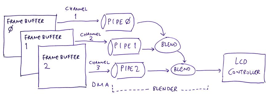
PinePhone's A64 Display Engine supports 3 Framebuffers (pic above). PinePhone's Blender combines the 3 Framebuffers into a single image for display.
Our job now is to configure the Blender so that it renders the Framebuffer correctly.
But we're using only one Framebuffer?
For now. Which makes the Blender Configuration a little simpler.
Up next: We'll set PinePhone's Hardware Registers to configure the Blender for a single Framebuffer...
-
Set Output Size
(Screen Size is 720 x 1440)
-
Set Input Size
(Framebuffer Size is 720 x 1440)
-
Set Fill Color
(Background is Opaque Black)
-
Set Input Offset
(X and Y Offsets are 0)
-
Set Blender Attributes
(For Alpha Blending)
-
Enable Blender
(For Blender Pipe 0)
Output Size
(BLD_SIZE / GLB_SIZE, Page 110 / 93)
We set the Output Size of our Blender to 720 x 1440 with this odd formula (that we've seen earlier)...
(height - 1) << 16 + (width - 1)
This is how we set the Hardware Registers: render.zig
// BLD_SIZE (Blender Output Size Setting)
// At BLD Offset 0x08C
// Set to (height-1) << 16 + (width-1)
// (DE Page 110)

const height_width: u32 =
  @intCast(u32, yres - 1) << 16  // yres is 1440
  | (xres - 1);                  // xres is 720
const BLD_SIZE = BLD_BASE_ADDRESS + 0x08C;
putreg32(height_width, BLD_SIZE);

// GLB_SIZE (Global Size)
// At GLB Offset 0x00C
// Set to (height-1) << 16 + (width-1)
// (DE Page 93)

const GLB_SIZE = GLB_BASE_ADDRESS + 0x00C;
putreg32(height_width, GLB_SIZE);
Input Size
According to the pic above, we're configuring Blender Pipe 0: render.zig
// Set Blender Input Pipe to Pipe 0
// (For Channel 1)
const pipe: u64 = channel - 1;
This is how we set the Input Size to 720 x 1440 for Blender Pipe 0: render.zig
// BLD_CH_ISIZE (Blender Input Memory Size)
// At BLD Offset 0x008 + N*0x10 (N=0 for Channel 1)
// Set to (height-1) << 16 + (width-1)
// (DE Page 108)

const BLD_CH_ISIZE = BLD_BASE_ADDRESS + 0x008 + pipe * 0x10;
putreg32(height_width, BLD_CH_ISIZE);
(We've seen height_width earlier)
Fill Color
We set the Background Fill Color for the Blender to Opaque Black: render.zig
// BLD_FILL_COLOR (Blender Fill Color)
// At BLD Offset 0x004 + N*0x10 (N=0 for Channel 1)
// ALPHA (Bits 24 to 31) = 0xFF
// RED   (Bits 16 to 23) = 0
// GREEN (Bits 8  to 15) = 0
// BLUE  (Bits 0  to 7)  = 0
// (DE Page 107)

const ALPHA: u32 = 0xFF << 24;  // Opaque
const RED:   u24 = 0    << 16;  // Black
const GREEN: u18 = 0    << 8;
const BLUE:  u8  = 0    << 0;
const color = ALPHA
  | RED
  | GREEN
  | BLUE;

const BLD_FILL_COLOR = BLD_BASE_ADDRESS + 0x004 + pipe * 0x10;
putreg32(color, BLD_FILL_COLOR);
Input Offset
We set the Input Offset of the Blender to X = 0, Y = 0: render.zig
// BLD_CH_OFFSET (Blender Input Memory Offset)
// At BLD Offset 0x00C + N*0x10 (N=0 for Channel 1)
// (DE Page 108)

const offset =
  @intCast(u32, yoffset) << 16  // yoffset is 0
  | xoffset;                    // xoffset is 0
const BLD_CH_OFFSET = BLD_BASE_ADDRESS + 0x00C + pipe * 0x10;
putreg32(offset, BLD_CH_OFFSET);
Blender Attributes
We set these (mysterious) Blender Attributes...
Coefficient for Destination Alpha Data Q[d] is 1-A[s]
Coefficient for Source Alpha Data Q[s] is 1
Coefficient for Destination Pixel Data F[d] is 1-A[s]
-
Coefficient for Source Pixel Data F[s] is 1
(Why?)
Like so: render.zig
// BLD_CTL (Blender Control)
// At BLD Offset 0x090 + N*4 (N=0 for Channel 1)
// BLEND_AFD (Bits 24 to 27) = 3
//   (Coefficient for destination alpha data Q[d] is 1-A[s])
// BLEND_AFS (Bits 16 to 19) = 1
//   (Coefficient for source alpha data Q[s] is 1)
// BLEND_PFD (Bits 8 to 11) = 3
//   (Coefficient for destination pixel data F[d] is 1-A[s])
// BLEND_PFS (Bits 0 to 3) = 1
//   (Coefficient for source pixel data F[s] is 1)
// (DE Page 110)

const BLEND_AFD: u28 = 3 << 24;  // Coefficient for destination alpha data Q[d] is 1-A[s]
const BLEND_AFS: u20 = 1 << 16;  // Coefficient for source alpha data Q[s] is 1
const BLEND_PFD: u12 = 3 << 8;   // Coefficient for destination pixel data F[d] is 1-A[s]
const BLEND_PFS: u4  = 1 << 0;   // Coefficient for source pixel data F[s] is 1
const blend = BLEND_AFD
  | BLEND_AFS
  | BLEND_PFD
  | BLEND_PFS;

const BLD_CTL = BLD_BASE_ADDRESS + 0x090 + pipe * 4;
putreg32(blend, BLD_CTL);
We're almost done with our Blender Configuration...
Enable Blender
(BLD_CH_RTCTL / BLD_FILL_COLOR_CTL / GLB_DBUFFER, Page 108 / 106 / 93)
Finally we enable Blender Pipe 0 (pic above): render.zig
// Set Blender Route
// BLD_CH_RTCTL (Blender Routing Control)
// At BLD Offset 0x080
//   P0_RTCTL (Bits 0 to 3) = 1 (Pipe 0 from Channel 1)
// (DE Page 108)

const P0_RTCTL: u4 = 1 << 0;  // Select Pipe 0 from UI Channel 1
const route = P0_RTCTL;

const BLD_CH_RTCTL = BLD_BASE_ADDRESS + 0x080;
putreg32(route, BLD_CH_RTCTL);  // TODO: DMB
(DMB means Data Memory Barrier)
We disable Pipes 1 and 2 since they're not used: render.zig
// Enable Blender Pipes
// BLD_FILL_COLOR_CTL (Blender Fill Color Control)
// At BLD Offset 0x000
//   P0_EN   (Bit 8)  = 1 (Enable Pipe 0)
//   P0_FCEN (Bit 0)  = 1 (Enable Pipe 0 Fill Color)
// (DE Page 106)

const P0_EN:   u9 = 1 << 8;  // Enable Pipe 0
const P0_FCEN: u1 = 1 << 0;  // Enable Pipe 0 Fill Color
const fill = P0_EN
    | P0_FCEN;

const BLD_FILL_COLOR_CTL = BLD_BASE_ADDRESS + 0x000;
putreg32(fill, BLD_FILL_COLOR_CTL);  // TODO: DMB
Our Framebuffer appears on PinePhone's Display when we apply the settings for the Display Engine: render.zig
// Apply Settings
// GLB_DBUFFER (Global Double Buffer Control)
// At GLB Offset 0x008
// DOUBLE_BUFFER_RDY (Bit 0) = 1
// (Register Value is ready for update)
// (DE Page 93)

const DOUBLE_BUFFER_RDY: u1 = 1 << 0;  // Register Value is ready for update
const GLB_DBUFFER = GLB_BASE_ADDRESS + 0x008;
putreg32(DOUBLE_BUFFER_RDY, GLB_DBUFFER);  // TODO: DMB
And that's all for rendering our Framebuffer!
Test PinePhone Display Driver
We're ready to test our Zig Display Driver on PinePhone!
Follow these steps to download NuttX RTOS (with our Zig Driver inside) to a microSD Card...
Connect our computer to PinePhone with a USB Serial Debug Cable. (At 115.2 kbps)
Boot PinePhone with NuttX RTOS in the microSD Card.
(NuttX won't disturb the eMMC Flash Memory)
At the NuttX Shell, enter this command to test our Zig Display Driver...
hello 1
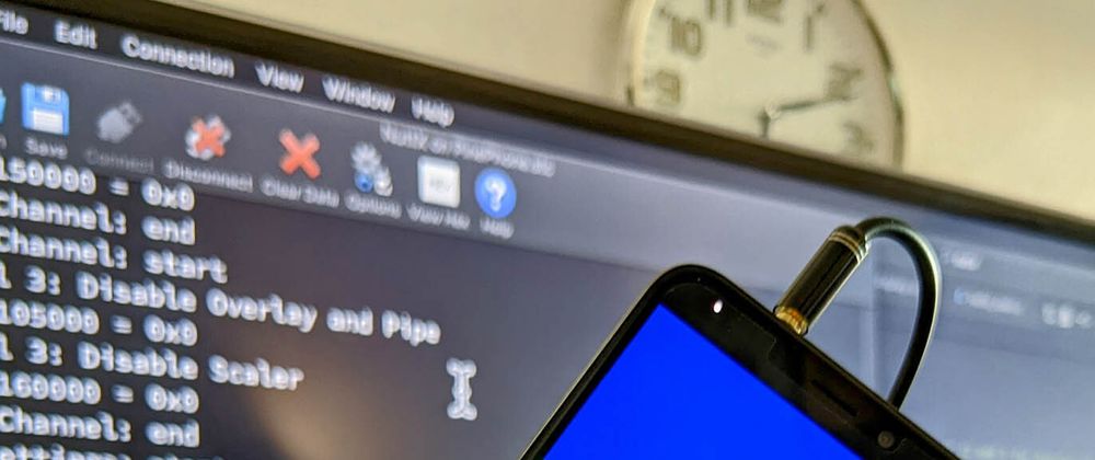
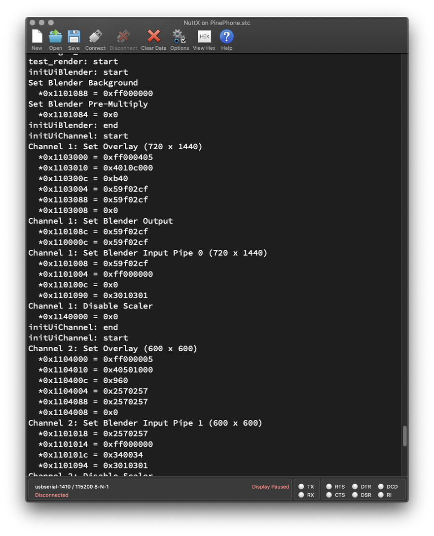
We should see our Zig Driver setting the Hardware Registers of the Allwinner A64 Display Engine (pic above)...
HELLO NUTTX ON PINEPHONE!
Shell (NSH) NuttX-11.0.0-RC2
nsh> hello 1
...
initUiChannel: start
Channel 1: Set Overlay (720 x 1440)
  *0x1103000 = 0xff000405
  *0x1103010 = 0x4010c000
  *0x110300c = 0xb40
  *0x1103004 = 0x59f02cf
  *0x1103088 = 0x59f02cf
  *0x1103008 = 0x0
Channel 1: Set Blender Output
Channel 1: Set Blender Input Pipe 0 (720 x 1440)
Channel 1: Disable Scaler
...
Channel 2: Disable Overlay and Pipe
Channel 2: Disable Scaler
...
Channel 3: Disable Overlay and Pipe
Channel 3: Disable Scaler
...
Set Blender Route
Enable Blender Pipes
Apply Settings
Why are Channels 2 and 3 disabled?
PinePhone supports 3 Framebuffers, but our demo uses only a single Framebuffer. (On Channel 1)
That's why we disabled Channels 2 and 3 for the unused Framebuffers.
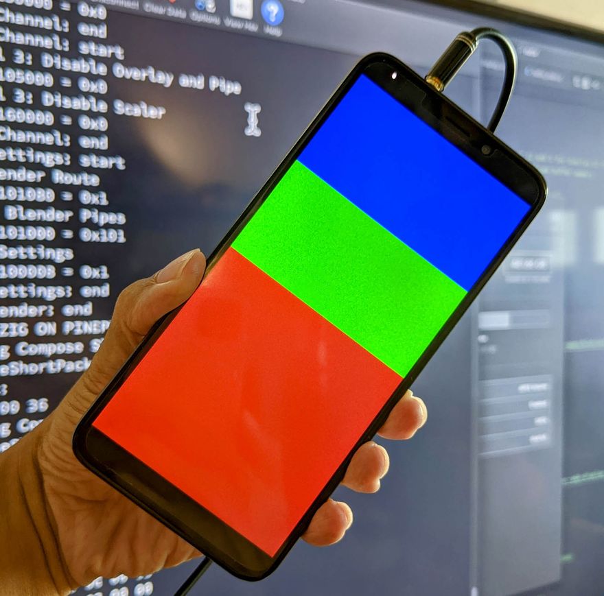
On PinePhone we see the Blue, Green and Red colour blocks. (Pic above)
Yep our Zig Display Driver renders graphics correctly on PinePhone! 🎉
We've successfully rendered a single Framebuffer. In the next chapter we push PinePhone's Display Hardware to the max with 3 Framebuffers.
The Blue / Green / Red Blocks look kinda bright. Didn't we set the Alpha Channel to be Semi-Transparent?
Aha! That's because we're rendering a Single Framebuffer, and we disregard the Alpha Channel for the Framebuffer.
That's why we configured the Framebuffer for XRGB 8888 instead of ARGB 8888. (See this)
In a while we'll render 2 Overlay Framebuffers configured for ARGB 8888. (To prove that the Alpha Channel really works!)
Multiple Framebuffers
Can we render Multiple Framebuffers?
Yep PinePhone's Display Hardware supports up to 3 Framebuffers (pic above)...
-
One Base Framebuffer
(Which we've just rendered)
-
Two Overlay Framebuffers
(Which we'll render now)
Let's walk through the steps to...
Allocate the 2 Overlay Framebuffers
Fill the pixels of the 2 Framebuffers
Render the 2 Framebuffers as Overlays
Allocate Framebuffers
Earlier we have allocated the Base Framebuffer...
-
Framebuffer 0: 720 x 1440 pixels (Fullscreen)
(With the Blue / Green / Red blocks)
Now we allocate 2 Overlay Framebuffers...
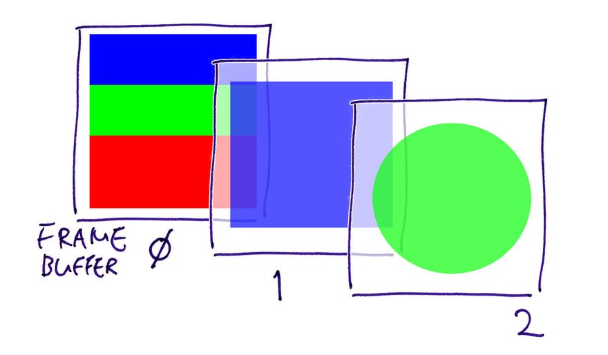
Framebuffer 1: 600 x 600 pixels (Square)
Framebuffer 2: 720 x 1440 pixels (Fullscreen)
Like so: render.zig
// Framebuffer 1: (First Overlay UI Channel)
// Square 600 x 600 (4 bytes per ARGB 8888 pixel)
var fb1 = std.mem.zeroes(  // Init to zeroes...
  [600 * 600] u32          // 600 x 600 pixels
);                         // (4 bytes per pixel: ARGB 8888)

// Framebuffer 2: (Second Overlay UI Channel)
// Fullscreen 720 x 1440 (4 bytes per ARGB 8888 pixel)
var fb2 = std.mem.zeroes(  // Init to zeroes...
  [720 * 1440] u32         // 720 x 1440 pixels
);                         // (4 bytes per pixel: ARGB 8888)
PinePhone supports Framebuffers that are not Fullscreen?
Yep Framebuffer 1 doesn't cover the screen completely, and it's OK!
Later we'll set the X and Y Offsets of Framebuffer 1, to centre it horizontally.
Fill Framebuffers
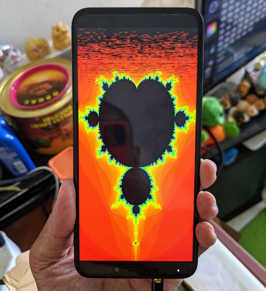
Let's fill the pixels of the 2 Overlay Framebuffers (pic above)...
Framebuffer 1: Semi-Transparent Blue Square
Framebuffer 2: Semi-Transparent Green Circle
This is how we fill Framebuffer 1 with a Semi-Transparent Blue Square: render.zig
// Init Framebuffer 1:
// Fill with Semi-Transparent Blue
i = 0;
while (i < fb1.len) : (i += 1) {
  // Colours are in ARGB 8888 format
  fb1[i] = 0x8000_0080;
}
(0x8000_0080 means Alpha = 0x80, Blue = 0x80)
And this is how we fill Framebuffer 2 with a Semi-Transparent Green Circle: render.zig
// Init Framebuffer 2:
// Fill with Semi-Transparent Green Circle
var y: usize = 0;
while (y < 1440) : (y += 1) {
  var x: usize = 0;
  while (x < 720) : (x += 1) {
    // Get pixel index
    const p = (y * 720) + x;
    assert(p < fb2.len);

    // Shift coordinates so that centre of screen is (0,0)
    const x_shift = @intCast(isize, x) - 360;
    const y_shift = @intCast(isize, y) - 720;

    // If x^2 + y^2 < radius^2, set the pixel to Semi-Transparent Green
    if (x_shift*x_shift + y_shift*y_shift < 360*360) {
      fb2[p] = 0x8000_8000;  // Semi-Transparent Green in ARGB 8888 Format
    } else {  // Otherwise set to Transparent Black
      fb2[p] = 0x0000_0000;  // Transparent Black in ARGB 8888 Format
    }
  }
}
(0x8000_8000 means Alpha = 0x80, Green = 0x80)
Note that pixels outside the circle are filled with 0. (Transparent Black)
Render Framebuffers
For our final step, we render all 3 Framebuffers: render.zig
// Init the UI Blender for PinePhone's A64 Display Engine
initUiBlender();

// Omitted: Init the Base UI Channel (as seen earlier)
initUiChannel(1, ...);

// Init the 2 Overlay UI Channels
inline for (overlayInfo) | ov, ov_index | {
  initUiChannel(
    @intCast(u8, ov_index + 2),  // UI Channel Number (2 and 3 for Overlay UI Channels)
    ov.fbmem,    // Start of frame buffer memory
    ov.fblen,    // Length of frame buffer memory in bytes
    ov.stride,   // Length of a line in bytes (4 bytes per pixel)
    ov.sarea.w,  // Horizontal resolution in pixel columns
    ov.sarea.h,  // Vertical resolution in pixel rows
    ov.sarea.x,  // Horizontal offset in pixel columns
    ov.sarea.y,  // Vertical offset in pixel rows
  );
}

// Set UI Blender Route, enable Blender Pipes
// and apply the settings
applySettings(channels);
(initUiBlender is defined here)
(applySettings is defined here)
Earlier we've seen initUiChannel for rendering a single Framebuffer.
We made some changes to support Multiple Framebuffers...
What's overlayInfo?
overlayInfo is the array that defines the properties of the 2 Overlay Framebuffers.
(fb_overlayinfo_s comes from NuttX RTOS)
Why "inline for"?
"inline for" expands (or unrolls) the loop at Compile-Time.
We need this because we're passing the arguments to initUiChannel as comptime Compile-Time Constants.
Test Multiple Framebuffers
We're ready for the final demo: Render Multiple Framebuffers with our Zig Driver on PinePhone!
Follow the earlier steps to download Apache NuttX RTOS to a microSD Card and boot it on PinePhone...
At the NuttX Shell, enter this command to render Multiple Framebuffers with our Zig Display Driver...
hello 3
Our Zig Driver sets the Hardware Registers of the Allwinner A64 Display Engine...
HELLO NUTTX ON PINEPHONE!
Shell (NSH) NuttX-11.0.0-RC2
nsh> hello 3
...
initUiChannel: start
Channel 1: Set Overlay (720 x 1440)
  *0x1103000 = 0xff000405
  *0x1103010 = 0x4010c000
  *0x110300c = 0xb40
  *0x1103004 = 0x59f02cf
  *0x1103088 = 0x59f02cf
  *0x1103008 = 0x0
Channel 1: Set Blender Output
Channel 1: Set Blender Input Pipe 0 (720 x 1440)
...
Channel 2: Set Overlay (600 x 600)
Channel 2: Set Blender Input Pipe 1 (600 x 600)
...
Channel 3: Set Overlay (720 x 1440)
Channel 3: Set Blender Input Pipe 2 (720 x 1440)
...
Set Blender Route
Enable Blender Pipes
Apply Settings
Note that Channels 2 and 3 are now enabled. This means that Framebuffers 1 and 2 will be visible.
On PinePhone we see the Blue, Green and Red colour blocks as before, plus 2 overlays...
-
Framebuffer 1: Semi-Transparent Blue Square
(Sorry the Top Half vanished into the Blue Block)
-
Framebuffer 2: Semi-Transparent Green Circle
(Pic above)
Our Zig Display Driver renders all 3 Framebuffers correctly on PinePhone yay!
The Green Circle looks really faint? Compared with the Blue Square?
That's because we applied a Global Alpha Value to the Green Circle...
This further reduces the opacity of the Semi-Transparent Pixels of the Green Circle, making it look really faint.
When we update the pixels in the Framebuffers, how do we refresh the display?
No refresh necessary, Framebuffer Updates are automatically pushed to PinePhone's Display!
That's because PinePhone's A64 Display Engine is connected to the Framebuffers via Direct Memory Access (DMA).
The pixel data goes directly from the Framebuffers in RAM to PinePhone's Display.
What's Next
Today we've shown that it's indeed possible to write a Zig Display Driver that talks directly to PinePhone's Hardware to render graphics.
(Bonus: Our Zig Driver includes an "Executable Specification" of PinePhone's Display Hardware Registers, with their addresses and values!)
The code we've seen today will eventually become the PinePhone Display Driver for Apache NuttX RTOS. Though some bits are still missing...
But now it's time to merge our code into NuttX Mainline! I'll explain the process in the next couple of articles, stay tuned!
Check out the other articles on NuttX RTOS for PinePhone...
Many Thanks to my GitHub Sponsors for supporting my work! This article wouldn't have been possible without your support.
Got a question, comment or suggestion? Create an Issue or submit a Pull Request here...
Appendix: Render Multiple Framebuffers
Earlier we've seen initUiChannel for rendering a single Framebuffer...
Then we modified initUiChannel to render 3 Framebuffers...
This Appendix explains the changes we made to render 3 Framebuffers. (Pic above)
Set Framebuffer Attributes
For Framebuffer Alpha: We configured Framebuffer 2 (Channel 3) to be Globally Semi-Transparent. (Global Alpha = 0x7F)
This means that the Global Alpha will be mixed with the Pixel Alpha. So the pixels will look extra faint for Framebuffer 2. (Green Circle, pic above)
For Pixel Format: We configured Framebuffers 1 and 2 (Channels 2 and 3) for Pixel Format ARGB 8888. (8-bit Alpha, 8-bit Red, 8-bit Green, 8-bit Blue)
This differs from Framebuffer 0, which we configured for XRGB 8888. (Alpha is ignored)
This is how we set the Framebuffer Attributes: render.zig
// Set Overlay (Assume Layer = 0)
// OVL_UI_ATTR_CTL (UI Overlay Attribute Control)
// At OVL_UI Offset 0x00
// LAY_GLBALPHA (Bits 24 to 31) = 0xFF or 0x7F
//   (Global Alpha Value is Opaque or Semi-Transparent)
// LAY_FBFMT (Bits 8 to 12) = 4 or 0
//   (Input Data Format is XRGB 8888 or ARGB 8888)
// LAY_ALPHA_MODE (Bits 1 to 2) = 2
//   (Global Alpha is mixed with Pixel Alpha)
//   (Input Alpha Value = Global Alpha Value * Pixel’s Alpha Value)
// LAY_EN (Bit 0) = 1 (Enable Layer)
// (DE Page 102)

const LAY_GLBALPHA: u32 = switch (channel) {  // For Global Alpha Value...
  1 => 0xFF,  // Channel 1: Opaque
  2 => 0xFF,  // Channel 2: Opaque
  3 => 0x7F,  // Channel 3: Semi-Transparent
  else => unreachable,
} << 24;  // Bits 24 to 31

const LAY_FBFMT: u13 = switch (channel) {  // For Input Data Format...
  1 => 4,  // Channel 1: XRGB 8888
  2 => 0,  // Channel 2: ARGB 8888
  3 => 0,  // Channel 3: ARGB 8888
  else => unreachable,
} << 8;  // Bits 8 to 12

const LAY_ALPHA_MODE: u3 = 2 << 1;  // Global Alpha is mixed with Pixel Alpha
const LAY_EN:         u1 = 1 << 0;  // Enable Layer
const attr = LAY_GLBALPHA
  | LAY_FBFMT
  | LAY_ALPHA_MODE
  | LAY_EN;

const OVL_UI_ATTR_CTL = OVL_UI_BASE_ADDRESS + 0x00;
putreg32(attr, OVL_UI_ATTR_CTL);
Next we configure the Blender...
Set Blender Route
Now that we render 3 Framebuffers instead of 1, we need to connect the Blender Pipes to their respective Framebuffers (Channels)...
Framebuffer 0 (Channel 1) connects to Blender Pipe 0
Framebuffer 1 (Channel 2) connects to Blender Pipe 1
-
Framebuffer 2 (Channel 3) connects to Blender Pipe 2
(Pic above)
Here's how we connect the pipes: render.zig
// Set Blender Route
// BLD_CH_RTCTL (Blender Routing Control)
// At BLD Offset 0x080
// If Rendering 3 UI Channels:
//   P2_RTCTL (Bits 8 to 11) = 3 (Pipe 2 from Channel 3)
//   P1_RTCTL (Bits 4 to 7)  = 2 (Pipe 1 from Channel 2)
//   P0_RTCTL (Bits 0 to 3)  = 1 (Pipe 0 from Channel 1)
// If Rendering 1 UI Channel:
//   P0_RTCTL (Bits 0 to 3) = 1 (Pipe 0 from Channel 1)
// (DE Page 108)

const P2_RTCTL: u12 = switch (channels) {  // For Pipe 2...
  3 => 3,  // 3 UI Channels: Select Pipe 2 from UI Channel 3
  1 => 0,  // 1 UI Channel:  Unused Pipe 2
  else => unreachable,
} << 8;  // Bits 8 to 11

const P1_RTCTL: u8 = switch (channels) {  // For Pipe 1...
  3 => 2,  // 3 UI Channels: Select Pipe 1 from UI Channel 2
  1 => 0,  // 1 UI Channel:  Unused Pipe 1
  else => unreachable,
} << 4;  // Bits 4 to 7

const P0_RTCTL: u4 = 1 << 0;  // Select Pipe 0 from UI Channel 1
const route = P2_RTCTL
  | P1_RTCTL
  | P0_RTCTL;

const BLD_CH_RTCTL = BLD_BASE_ADDRESS + 0x080;
putreg32(route, BLD_CH_RTCTL);  // TODO: DMB
(channels is 3 when we render 3 Framebuffers)
Enable Blender Pipes
(BLD_FILL_COLOR_CTL, Page 106)
After connecting the Blender Pipes, we enable all 3 Blender Pipes: render.zig
// Enable Blender Pipes
// BLD_FILL_COLOR_CTL (Blender Fill Color Control)
// At BLD Offset 0x000
// If Rendering 3 UI Channels:
//   P2_EN   (Bit 10) = 1 (Enable Pipe 2)
//   P1_EN   (Bit 9)  = 1 (Enable Pipe 1)
//   P0_EN   (Bit 8)  = 1 (Enable Pipe 0)
//   P0_FCEN (Bit 0)  = 1 (Enable Pipe 0 Fill Color)
// If Rendering 1 UI Channel:
//   P0_EN   (Bit 8)  = 1 (Enable Pipe 0)
//   P0_FCEN (Bit 0)  = 1 (Enable Pipe 0 Fill Color)
// (DE Page 106)

const P2_EN: u11 = switch (channels) {  // For Pipe 2...
  3 => 1,  // 3 UI Channels: Enable Pipe 2
  1 => 0,  // 1 UI Channel:  Disable Pipe 2
  else => unreachable,
} << 10;  // Bit 10

const P1_EN: u10 = switch (channels) {  // For Pipe 1...
  3 => 1,  // 3 UI Channels: Enable Pipe 1
  1 => 0,  // 1 UI Channel:  Disable Pipe 1
  else => unreachable,
} << 9;  // Bit 9

const P0_EN:   u9 = 1 << 8;  // Enable Pipe 0
const P0_FCEN: u1 = 1 << 0;  // Enable Pipe 0 Fill Color
const fill = P2_EN
  | P1_EN
  | P0_EN
  | P0_FCEN;

const BLD_FILL_COLOR_CTL = BLD_BASE_ADDRESS + 0x000;
putreg32(fill, BLD_FILL_COLOR_CTL);  // TODO: DMB
(channels is 3 when we render 3 Framebuffers)
Appendix: Upcoming Features in PinePhone Display Driver
We have completed in Zig three major chunks of PinePhone's Display Driver...
-
Initialise PinePhone's ST7703 LCD Controller
-
Initialise PinePhone's Allwinner A64 Display Engine
-
Render Graphics on PinePhone's Allwinner A64 Display Engine
Some features are still missing from our Zig Display Driver...
-
Initialise PinePhone's Allwinner A64 Timing Controller (TCON0)
-
Initialise PinePhone's Allwinner A64 MIPI Display Serial Interface (including MIPI DPHY)
-
Turn on PinePhone's Backlight
We hope to implement the missing features and complete the documentation for PinePhone's Display Driver. Stay Tuned!
(The Guitar And The Fish!)


Top comments (2)
Hell yeah!
That's a damn cool tech demo! I should try that on my on PinePhone, wanted to play around with Zig on it anyways.
Thanks for the detailled writeup!
Thanks for reading! :-)