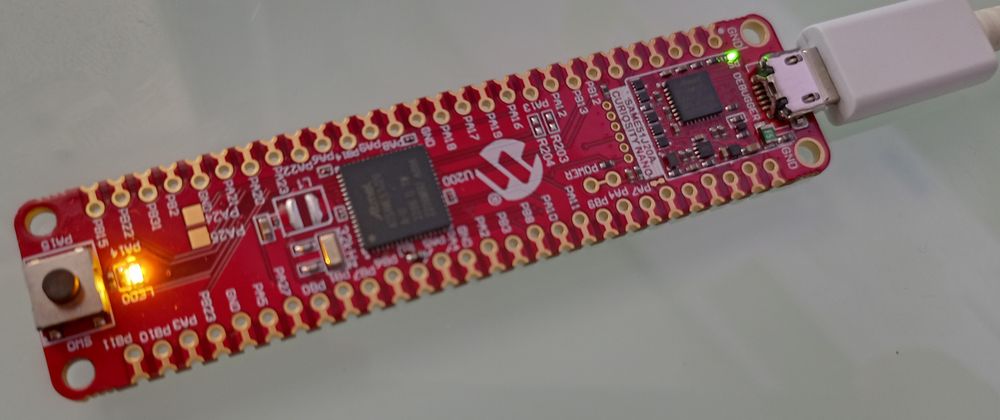
Last time we made the user LED of the Curiosity Nano board blink. In this post we're going to add (blocking) UART support to MicroZig, so we can interact with the board over a serial terminal.
MicroZig defines a UART interface in src/core/uart.zig. To use it for our chip we must define a uart struct that specifies the supported DataBits (bits send between the start and stop bit), the number of StopBits and the Parity mode, as well as a Uart function.
// src/modules/chips/atsame51j20a/atsame51j20a.zig

/// Unique definitions for the chip, used by the microzig.uart.Config struct.
pub const uart = struct {
    /// USART character size (p. 859).
    pub const DataBits = enum(u3) {
        eight = 0,
        nine = 1,
        five = 5,
        six = 6,
        seven = 7,
    };

    /// USART stop bits (p. 859).
    pub const StopBits = enum(u1) {
        one = 0,
        tow = 1,
    };

    /// USART parity mode (p. 858).
    pub const Parity = enum(u1) {
        even = 0,
        odd = 1,
    };
};
The Uart function returns an anonymous struct containing an initialization function init and four other functions for sending and receiving data via UART.
-
canWrite- Checks if the DATA register is empty and ready to be written. -
tx- Transmit one chunk of data by writing it into the DATA register. -
canRead- Returns true if there is unread data in the DATA register. -
rx- Read one chunk of received data.
// src/modules/chips/atsame51j20a/atsame51j20a.zig

pub fn Uart(comptime index: usize, comptime pins: micro.uart.Pins) type {
    if (pins.tx != null or pins.rx != null)
        @compileError("TODO: custom pins are not currently supported");

    return struct {
        const UARTn = switch (index) {
            5 => regs.SERCOM5.USART_INT,
            else => @compileError("Currently only SERCOM5:USART_INT supported."),
        };
        const Self = @This();

        pub fn init(config: micro.uart.Config) !Self {

            // ...

            return Self{};
        }

        pub fn canWrite(self: Self) bool {
            _ = self;
            // The DRE flag ist set when DATA is empty and ready to be written.
            // The DATA register should only be written to when INTFLAG.DRE is set.
            return UARTn.INTFLAG.read().DRE == 1;
        }
        pub fn tx(self: Self, ch: u8) void {
            while (!self.canWrite()) {} // Wait for Previous transmission
            UARTn.DATA.* = ch; // Load the data to be transmitted
        }

        pub fn canRead(self: Self) bool {
            _ = self;
            // The RXC flag ist set when there are unread data in DATA.
            return UARTn.INTFLAG.read().RXC == 1;
        }
        pub fn rx(self: Self) u8 {
            _ = self;
            while (!self.canRead()) {} // Wait till the data is received
            return @intCast(u8, UARTn.DATA.*); // Read received data
        }
    };
}
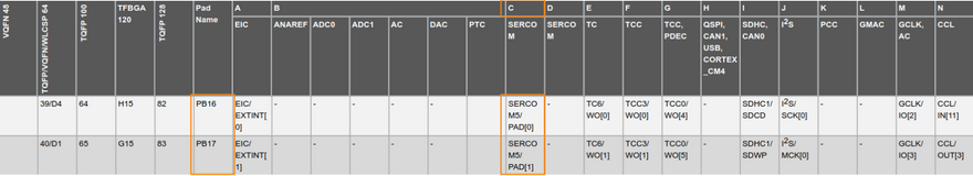
The onboard debugger of the Curiosity Nano includes a virtual COM port interface over UART, using PB16 (TX) and PB17 (RX). By looking at the datasheet on page 34 (I/O Multiplexing and Considerations) we see that both pins are connected to SERCOM5 (peripheral function C). For now, let's only support UART on SERCOM5.
The functions canWrite, tx, canRead and rx should be pretty self-explanatory
but init is a little bit more complex.
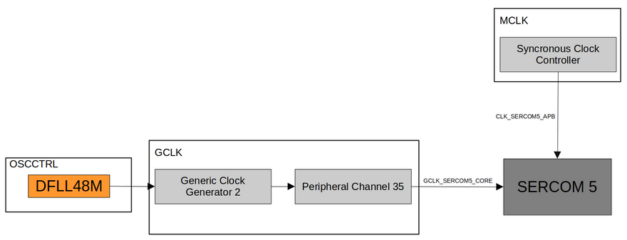
Clock distribution
For SERCOM5 to work we need a clock source to drive it. The chip we use gives us a variety of options, including the external crystal oscillator XOSC0 and XOSC1. We're going to use the Digital Frequency Locked Loop (DFLL48M), which is also the default clock for generating GCLK_MAIN after startup.
To clock SERCOM5 we use the Generic Clock Generator 2 (GCLK2) and select DFLL48M as its source.
A Generic Clock Generator is a programmable prescaler that can use any of the
system clock sources as a time base (data sheet p. 136).
pub fn gclk2Init() void {
    regs.GCLK.GENCTRL[2].modify(.{
        .DIV = 1,
        .SRC = 6, // DFLL48M generator clock source
        .GENEN = 1, // Enable generator
    });

    while (regs.GCLK.SYNCBUSY.read().GENCTRL & 2 != 0) {
        // wait for sync
    }
}
After setting up GCLK2, we feed its Generic Clock into Peripheral Channel 35 (SERCOM5 Core) which is connected to SERCOM5. The SERCOM5 interface is clocked by CLK_SERCOM5_APB, so we need to set SERCOM5_ in the APBDMASK register to 1, otherwise, the interface registers can't be read or written.
pub fn init(config: micro.uart.Config) !Self {
    switch (index) {
        5 => {
            gclk2Init();

            regs.GCLK.PCHCTRL[35].modify(.{
                .GEN = 2, // Generic clock generator 2 (see p. 156)
                .CHEN = 1, // Enable peripheral channel
            });

            // When the APB clock is not provided to a module, its
            // registers cannot be read or written.
            regs.MCLK.APBDMASK.modify(.{ .SERCOM5_ = 1 });

            // Enable the peripheral multiplexer selection.
            regs.PORT.GROUP[1].PINCFG[16].modify(.{ .PMUXEN = 1 });
            regs.PORT.GROUP[1].PINCFG[17].modify(.{ .PMUXEN = 1 });

            // Multiplex PB16 and PB17 to peripheral function C, i.e.
            // SERCOM5 (see page 32 and 823).
            regs.PORT.GROUP[1].PMUX[8].modify(.{ .PMUXE = 2, .PMUXO = 2 });
        },
        else => unreachable,
    }

    // ...

    return Self{};
}
As you can see we also enable peripheral multiplexing for PB16 and PB17. This means in general that the pins are now controlled by SERCOM5.
Configure USART
After configuring the clock and pins, the last thing that remains is initializing USART on SERCOM5 correctly (data sheet p. 837 - 34.6.2.1).
pub fn init(config: micro.uart.Config) !Self {
    switch (index) {

    // ...

    // Some of the registers are enable-protected, meaning they can only
    // be written when the USART is disabled.
    UARTn.CTRLA.modify(.{ .ENABLE = 0 });

    // Wait until synchronized.
    while (UARTn.SYNCBUSY.read().ENABLE != 0) {}

    // Select USART with internal clock (0x1).
    UARTn.CTRLA.modify(.{
        .MODE = 1, // Select USART with internal clock (0x01)
        .CMODE = 0, // Select asynchronous communication mode (0x00)
        // Pin selection (data sheet p. 854)
        .RXPO = 1, // SERCOM PAD[1] is used for data reception
        .TXPO = 0, // SERCOM PAD[0] is used for data transmition
        .DORD = 1, // Configure data order (MSB = 0, LSB = 1)
        .IBON = 1, // Immediate buffer overflow notification
        .SAMPR = 0, // 16x over-sampling using arithmetic baud rate generation
    });

    // Configure parity mode.
    if (config.parity != null) {
        // Enable parity mode.
        UARTn.CTRLA.modify(.{ .FORM = 1 }); // USART frame with parity
        UARTn.CTRLB.modify(.{ .PMODE = @enumToInt(config.parity.?) });
    } else {
        // Disable parity mode.
        UARTn.CTRLA.modify(.{ .FORM = 0 }); // USART frame
    }

    // Write the Baud register (internal clock mode) to generate the
    // desired baud rate.
    UARTn.BAUD.* = asyncArithmeticBaudToRegister(config.baud_rate, 48_000_000);

    UARTn.CTRLB.modify(.{
        .CHSIZE = @enumToInt(config.data_bits), // Configure the character size filed.
        .SBMODE = @enumToInt(config.stop_bits), // Configure the number of stop bits.
        .RXEN = 1, // Enable the receiver
        .TXEN = 1, // Enable the transmitter
    });

    while (UARTn.SYNCBUSY.raw != 0) {}

    // Enable the peripheral.
    UARTn.CTRLA.modify(.{ .ENABLE = 1 });
    while (UARTn.SYNCBUSY.raw != 0) {}

    return Self{};
}
The baud-rate generator generates internal clocks for asynchronous and synchronous communication. The output frequency (fBAUD) is determined by the Baud register (BAUD) setting and the baud reference frequency (fref). The baud reference clock is the serial engine clock, and it can be internal or external (data sheet p. 830).
-
fBAUD- The expected baud rate (e.g. 115200) -
fref- The reference frequency (48MHz in our case)
To calculate the required BAUD value based on fBAUD and fref we can use the formula $BAUD = 65536 * (1 - 16 * (fBAUD / fref))$.
/// Calculate the BAUD register value based on the the expected output frequency
/// `fbaud` and the baud reference frequency `fref` (see data sheet p. 830).
pub fn asyncArithmeticBaudToRegister(fbaud: u32, fref: u32) u16 {
    const fb = @intToFloat(f64, fbaud);
    const fr = @intToFloat(f64, fref);
    const res = 65536.0 * (1.0 - 16.0 * (fb / fr));

    return @floatToInt(u16, res);
}
and that's it.
Serial Communication
To set up UART over SERCOM5 within our main function we call Uart passing it 5 as the index and then call the init function on it. As options, we select a baud rate of 115200, one stop bit, no parity bit, and eight data bits.
By calling the writer function on uart we get a std.io.Writer we can use as usual.
const micro = @import("microzig");

const status_led_pin = micro.Pin("PA14");

pub fn main() !void {
    const status_led = micro.Gpio(status_led_pin, .{
        .mode = .output,
        .initial_state = .low,
    });
    status_led.init();

    var uart = micro.Uart(5, .{ .tx = null, .rx = null }).init(.{
        .baud_rate = 115200,
        .stop_bits = .one,
        .parity = null,
        .data_bits = .eight,
    }) catch |err| {
        blinkError(status_led, err);

        micro.hang();
    };

    var out = uart.writer();

    while (true) {
        busyloop();
        status_led.toggle();
        try out.writeAll("Hello, MicroZig!\n\r");
    }
}

fn blinkError(led: anytype, err: micro.uart.InitError) void {
    var blinks: u3 =
        switch (err) {
        error.UnsupportedBaudRate => 1,
        error.UnsupportedParity => 2,
        error.UnsupportedStopBitCount => 3,
        error.UnsupportedWordSize => 4,
    };

    while (blinks > 0) : (blinks -= 1) {
        led.toggle();
        micro.debug.busySleep(1_000_000);
        led.toggle();
        micro.debug.busySleep(1_000_000);
    }
}

fn busyloop() void {
    const limit = 6_000_000;

    var i: u32 = 0;
    while (i < limit) : (i += 1) {
        @import("std").mem.doNotOptimizeAway(i);
    }
}
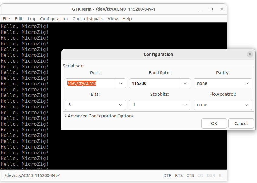
If you connect to the board using a serial communication tool (e.g. GTKterm) you should see the string Hello, MicroZig! displayed on the screen.
Known issues
Regz might add too much padding after PORT 0, so make sure that the padding is exactly 0x20. Otherwise you won't be able to configure
PB16andPB17correctly (that gave me some headaches).When a terminal connects on the host, it must assert the DTR signal.
Build
If you've installed edbg you can use the following build file to program the Curiosity Nano using the zig build edbg command.
const std = @import("std");
const microzig = @import("libs/microzig/src/main.zig");

pub fn build(b: *std.build.Builder) void {
    const backing = .{
        .chip = microzig.chips.atsame51j20a,
    };

    var exe = microzig.addEmbeddedExecutable(b, "zig-ctap", "src/main.zig", backing, .{
        // optional slice of packages that can be imported into your app:b
        // .packages = &my_packages,
    });

    exe.setBuildMode(.ReleaseSmall);
    exe.inner.strip = true;
    exe.install();

    // ########################################################################
    // Use `zig build edbg` to:
    //   1. build the raw binary
    //   2. program the device using edbg (Microchip SAM)
    // ########################################################################

    const bin = exe.installRaw("firmware.bin", .{});

    const edbg = b.addSystemCommand(&[_][]const u8{
        "sudo", "edbg", "-b", "-t", "same51", "-pv", "-f", "zig-out/bin/firmware.bin",
    });
    edbg.step.dependOn(&bin.step);

    const program_step = b.step("edbg", "Program the chip using edbg");
    program_step.dependOn(&edbg.step);
}
Note: The
buildfunction uses some wrapper functions from the MicroZig
pull request #77.


Top comments (0)