EDIT: a more detailed description on how to add a new chip to MicroZig can be found here
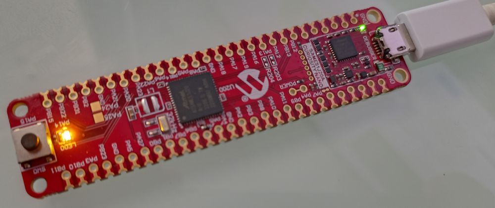
This post is about my process of writing a simple program for the SAM E51 Curiosity Nano board. The goal is to turn the User LED (pin PA14) on.
I used MicroZig and Regz to get started.
Code generation using Regz
The board uses the ATSAME51J20A (Arm M4f) processor and because MicroZig doesn't support it yet, the first step was to grap the corresponding SVD File and generate Zig code from it using Regz.
$ regz ATSAME51J20A.svd > registers.zig
Note: I found that the generated code won't
compile because the addresses (e.g.base_address)
used are of typecomptime_int. I could fix it by
casting the addresses to pointers using@intToPtr,
e.g.pub const base_address = @intToPtr([*]u8, 0x41008000);..\libs\microzig\src\modules\chips\atsame51j20a\registers.zig:10953:12: error: expected pointer, found 'comptime_int' }, base_address); ^
Chip specific code
Next, I had to define a parsePin function as well as some additional GPIO functions, which MicroZig is going to use to e.g. set the direction of a pin.
// atsame51j20a.zig
pub const cpu = @import("cpu");
pub const micro = @import("microzig");
pub const chip = @import("registers.zig");

const regs = chip.registers;
pub usingnamespace chip;

pub const clock_frequencies = . {
    .cpu = 120_000_000, // Arm Cortex-M4 runs at 120 MHz
};

/// Get access to the pin specified by `spec`.
///
/// - `spec`: P{port}{pin}
///     - `port`: A, B
///     - `pin`: 0..31
pub fn parsePin(comptime spec: []const u8) type {
    const invalid_format_msg = "The given pin '" ++ spec ++ "' has an invalid format. Pins must follow the format \"P{Port}{Pin}\" scheme.";

    if (spec[0] != 'P')
        @compileError(invalid_format_msg);
    if (spec[1] < 'A' or spec[1] > 'B') // J = 64 Pins; 2 Ports
        @compileError("Unknown port '" ++ spec[1..2] ++ "'. Supported ports: A, B.");

    return struct {
        // Try to parse the given pin number as u5, i.e. a value in '0'..'31'.
        const pin_number: u5 = @import("std").fmt.parseInt(u5, spec[2..], 10) catch @compileError(invalid_format_msg);
        const pin_mask: u32 = (1 << pin_number);
        // Port is either 'A' or 'B'.
        const port_number: usize = if (spec[1] == 'A') 0 else 1;
        const gpio_port = @field(regs.PORT, "GROUP");
    };
}
The parsePin function takes a string like PA14 and extracts the port and pin number from it. The ports are defined in registers.zig (created using Regz) as an array of two packed structs, where A corresponds to index 0 and B to 1.
 /// Port Module
    pub const PORT = struct {
        pub const base_address = @intToPtr([*]u8, 0x41008000);
        pub const version = "U22102.2.0";

        pub const GROUP = @ptrCast(*volatile [2]packed struct {
            /// Data Direction
            DIR: u32,

            /// Data Direction Clear
            DIRCLR: u32,

            /// Data Direction Set
            DIRSET: u32,

            // ...

        }, base_address);
    };
The functions setOutput and setInput can be used to control the direction of a pin and the functions read and write are for reading from and writing to the specified pin.
// atsame51j20a.zig
pub const gpio = struct {
    pub fn setOutput(comptime pin: type) void {
        pin.gpio_port[pin.port_number].DIRSET |= pin.pin_mask;
    }

    pub fn setInput(comptime pin: type) void {
        pin.gpio_port[pin.port_number].DIRCLR |= pin.pin_mask;
    }

    pub fn read(comptime pin: type) micro.gpio.State {
        _ = pin;
        return micro.gpio.State.low;
    }

    pub fn write(comptime pin: type, state: micro.gpio.State) void {
        switch (state) {
            .high => pin.gpio_port[pin.port_number].OUTSET |= pin.pin_mask,
            .low => pin.gpio_port[pin.port_number].OUTCLR |= pin.pin_mask,
        }
    }
};
Then I placed registers.zig and atsame51j20a.zig in a new Folder atsame51j20a under microzig/src/modules/chips, which I added as a submodule to my project.
Define the chip
Last but not least I had to define the chip in microzig/src/chips.zig. The memory regions are from
the SAM D5x/E5x Family Data Sheet page 53.
// chips.zig
pub const atsame51j20a = Chip{
    .name = "ATSAME51J20A",
    .path = root_path ++ "chips/atsame51j20a/atsame51j20a.zig",
    .cpu = cpus.cortex_m4,
    .memory_regions = &.{
        // SAM D5x/E5x Family Data Sheet page 53
        MemoryRegion{ .offset = 0x00000000, .length = 1024 * 1024, .kind = .flash },
        MemoryRegion{ .offset = 0x20000000, .length = 256 * 1024, .kind = .ram },
    },
};
Setup the build script
I followed the instructions of the MicroZig readme to setup the build script.
const std = @import("std");
const microzig = @import("libs/microzig/src/main.zig");

pub fn build(b: *std.build.Builder) void {
    const backing = .{
        .chip = microzig.chips.atsame51j20a,
    };

    const exe = microzig.addEmbeddedExecutable(
        b,
        "zig-ctap",
        "src/main.zig",
        backing,
        .{
            // optional slice of packages that can be imported into your app:b
            // .packages = &my_packages,
        }
    );

    exe.inner.setBuildMode(.ReleaseSmall);
    exe.inner.install();
}
A simple main
As already mentioned the goal is to compile a program successfully and use it to turn the User LED (PA14) on.
const micro = @import("microzig");

// Get the pin of the user led; Port A, Pin 14.
// This will call `parsePin` under the hood.
const status_led_pin = micro.Pin("PA14");

pub fn main() !void {
    // setup the status_led_pin as GPIO pin
    const status_led = micro.Gpio(status_led_pin, .{
        .mode = .output,
        .initial_state = .low,
    });
    // this will call `setOutput` and `write(.low)`
    // under the hood.
    status_led.init();

    while (true) {}
}
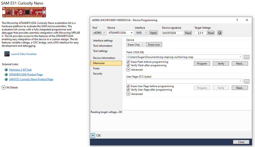
Flash program
After building the project using zig build I used the Device Programming Ctrl + Shift + P feature of Microchip Studio (Windows) to flash the device.
If you know a program on linux which I can use to flash the device please let me know :)
You can find the code on Github.


Top comments (1)
Thank you for sharing! Seems that the Zig Embedded Group is starting to get some traction, nice!